A few photos of slow progress...


A few photos of slow progress...
I think it's an interesting idea and something that you could look into in the future, but there are few things to keep in mind.Originally Posted by VinylGroove

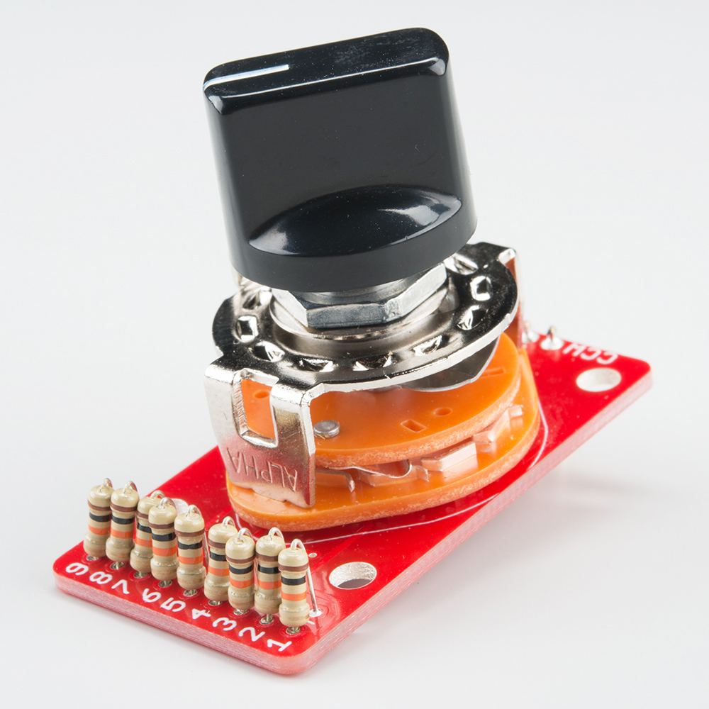
The switched attenuators you're showing in the photos are relatively easy to pull off since they are often meant for line-level applications and are sized for 1/4W to 1W metal film resistors. You'd need something more substantial for a speaker crossover application (remember the resistors in the crossover are rated for 12W+ each), and that could get prohibitively large.
It would have to be *both* resistors that get swapped if you want to dial up and down the attenuation properly, though - that's the trick. A L-pad is a variable voltage divider that maintains a constant load (8 ohm or 16 ohm, most commonly) as seen by the amplifier. If you could imagine turning the knob on a variable L-pad and picture the equivalent voltage divider in your head, both the series resistor leg and the shunt resistor leg would be changing in value to maintain that constant load. You can also see this by messing around with an L-pad calculator like this one: http://www.sengpielaudio.com/calculator-Lpad.htm
Overall, I think you'll find the new L-pads you've purchased from Parts Express to be reliable and an improvement on the old, dirty ones. I started with fresh ones three years ago now in my external crossover units, and they still have yet to exhibit any audible crackles when adjusting, channel dropouts, etc.
You'll find the adjustability very valuable when dialing the system in for the first time, and then can explore fixed resistor options if you wish. Just make sure you use a calculator such as the above and remember which impedance loads you're trying to match.
https://www.echomountainaudio.com
Charge-Coupled Crossover PCBs
Looks like progress! That's awesome.
Just a thought (if you think you might display these in an external box in the future): if you don't like the look of bare wire, you can always mount the wire shorts, like the one you have across R13, on the bottom side of the board. Same thing for the L-pad and input/output wiring when you get there. I route it on bottom side of the board, bring it up through the plated through holes from the bottom side, and solder on the top. Keeps everything looking tidy.
https://www.echomountainaudio.com
Charge-Coupled Crossover PCBs
I didn't think about the 3rd terminal on the L-pads and it being more than just an inline resistor. Makes sense.
I don't mind seeing the shorted wire and it makes it easier to see what you have going on if it's on the top, but something to keep in mind for future projects.
Fair point, indeed!
https://www.echomountainaudio.com
Charge-Coupled Crossover PCBs
Well Nelson Pass wrote in his L300 article he could not detect any sonic change with the L pads. The advantage of a switching L pad is to have repeatable know changes in the driver level.
But do you need to mess with making a switched L pad?
A few tips.
No one setting of the L pads is going to necessarily going suit everyone in every situation. Some rooms will dictate lower or higher L pad settings. Equipment like a valve preamp and power amps in a bi amp situation could potentially need higher L pad settings.
So the flexibility of an L Pad in necessary.
However, you do need to have the drivers reasonably well matched in level. Right.
You can do this by ear by listening carefully to the tonal balance while turning the L pad of one driver at a time. Do this close to the loudspeaker to avoid the reverberation of the room. You can made adjustments to the Lpads later to deal with that.
For example with the horn and slot turned off listen for the mid cone driver and woofer blend that you prefer near the loudspeaker. The bass forms the foundation and much of the emotion in most music. So setting the bass / mid balance is a logical place to start.
By adopting this approach your ears are telling you what you are actually hearing. Thats important because loudspeaker placement in a room significantly effects the bass balance.
Then introduce the horn. By turning the horn L pad up and down you will be able to determine the blend you prefer in your environment. The upper mid range is what adds presence to tonal character. Then introduce the slot 2405. The slot 2405 adds details and ambiance to a musical presentation. By adjusting the 2405 L pad find the position you prefer.
Now the fun part. Recording your L pad preferences.
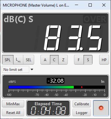
Ideally if you want to make a change to any of these L pad settings you need to record the changes. Using a Studio Six down load or similar you can make spot frequency test tones to measure increments of change in the L pads position. This can be done with a high degrees of accuracy using a low cost spl sound level meter. These digital spl meters can measure small changes in sound level accurately.
For example you might want to try increasing the horn up or down slightly but by a known amount. With a 5,000 hertz sine wave position the spl meter right in front of the horn lens about 2-3 inches from the meter. Turn the horn L pad up until the spl meter shows an increase of 1 db. You can then record you changes and go back to them later.
Caveat. This will send the family nuts. Send them off to a movie.
For the mid cone driver use a 600 hertz sine wave. For the 2405 use 8000 hertz. Remember to put the spl mic right in front of each driver.
With this process we are only interested in measuring the changes made in the spl level of each driver. You cant easily do this with a room frequency analyser. They dont have the resolution.
To determine the overall L pad attenuation of each L pad complete the following procedure.
Using the same spot frequencies for the mid, horn and 2405 each L pad at your preferred Lpad positions adjust the level to a round spl level in the spl meter. Say 90 db. Then turn the L pad up full. Note the change in db. Repeat for the other drivers.
Using this data you can now set the drivers on the other channel to exactly the same levels by turning the Lpad from full down by the measured amount.
You will find the tonal balance between the left and right channels much improved.
Once you have determined the L pad settings and the net attenuation of each L pad the fixed resister values can be determined.
https://www.instrumentchoice.com.au/...d-level-meters
I dont claim to have been the inventor of this approach but this explanation is mine.
Copyright Ian Mackenzie Audio 2022.
Very useful info. Thanks. I never thought of doing that with individual drivers before.
This might seem odd to some people, but I only trust my ears to dial my system into 1 type of music at a time. I can always get that sounding great, but when I try something different I often realize I'm off in my settings, so I chase my tail. And when you compound the possibilities of 3 L pads, active crossover, preamp settings and for each of them it's both the levels you set and the relationship between them and others - and you can never trust a knob at 12 oclock to be the baseline either.
It will be interesting to use a noise generator and a mic/software to visually see the output at all freq levels to see where it's weak/strong - and get it as close to flat as possible, then my thought was to mostly use the preamp settings for bass and treble from that point on.
So true. It's best to write down all the settings one uses when trying different configurations, to be able to return to the baseline.
The method that Ian describes above with the SPL meter on individual drivers is a good one; we followed a similar procedure on dialing in my 4344s when he visited my home a few years back, and I've done it subsequently when making tweaks to the system. The "software" SPL meter within REW (https://www.roomeqwizard.com/help/he.../splmeter.html) works well for this too, once you have a calibrated measurement microphone on hand. The handheld meters can obviously come in handy and are convenient when you don't want to bust out the laptop.
https://www.echomountainaudio.com
Charge-Coupled Crossover PCBs
No problem.
This is diy and any goes.
On the sanity aspect note that a software based analyser is only a snap shot like a photo at a given moment in time. It not a true indicator of how your ears are being effected by the reverberation of your room which is at least half of what you hear.
This is because the loudspeaker emits sound not only directly to your ears but to most surfaces in your room. These reflections can be analogous to beams of light bouncing off the walls, floor and ceiling at all frequencies above the Schroder frequency of about 350-400 hertz. Because each reflected ray of sound has a delay interval typically 500-1000 ms you ears actually hear this. Its like a shadow of the direct sound at a lower level.
For most people in their living room there is nothing you can do about this accept sit in a convenient position to listen to your loudspeakers.
Thus while from a technical standpoint a frequency graph might look like a good yard stick to make an assessment its actual use of it needs to have a place. Its not the final arbiter of whats going to be enjoyable in your room.
I agree the old school bass and treble is useful.
From a scientific perspective Harman has come up with some guidelines called a room curve which is very similar to slight turn to the left of a treble control and modest bass boost. Of course Harman are selling you the idea that they discovered this curve so you buy their equipment and loudspeakers. But its been used for decades on traditional integrated amplifiers. The wankers.
In the end trust your ears and look at the curves only if you hear something wrong. It it aint wrong dont mess with it .
Edit the 500-1000 ms referred to above is the time taken for the reflections in a small room (less than the size of a in door basket ball court or meeting hall) to reduce to an inaudible level. These reflections also tie in with the dispersion characteristics of a loudspeaker
Tip
Toe in your 4343s about 10-15 degrees and place the enclosures 2.00 - 2.5 metres apart if possible. Tell your wife if she loves you then its okay.
Ideally the enclosures should be located at non equal distances to the rear and side walls. Your listening height is best if level with the lower lip of the 2308 horn lens. Pick a listening position equivalent to an equilateral triangle. Grab a glass of red wine and enjoy 😊 it.
This is the thing.
We all read reviews of phono preamps. Its generally agreed the tighter the tolerance of variation with the RIAA equalisation get better. Its an important performance criteria.
The measurement is +-0.5 db or better.
Generally we to are more susceptible to shifts in tonal balance over two or more octaves than small dips and peaks. So, if you have a four way loudspeaker the overall driver level balance analogous to a phono stage EQ. If the horn is above the mid by two db or more its going to effect the overall tonal balance. Given the caveat of your room on the acoustics you still need a degree of precision to set the L pads and match both the left and right channels.
If you use a room response analyser at 3 metres youd be lucky to see +-3 db.
Therefore l recommend the above spl meter on a tripod. These digital meters can measure fractions of one db.
REW is good tool to obtain overall system measurements averaged across five or more locations near you listening position. Its also good for near field driver response measurements. The most recent version of REW has tools for advanced acoustic analysis.
Thats not much use unless you can made real chances to your room acoustics.
If you have DIRAC or another home theatre receiver room calibration program you can experiment with the auto room set up.
FWIW, I used the actual SPL meter function in REW, with fixed frequencies pretty much exactly as you described above, and it worked well in tandem with my calibrated microphone on a microphone boom stand or tripod. The measurements were repeatable and high-resolution. The interface is modeled after the handheld SPL meters.
https://www.roomeqwizard.com/help/he.../splmeter.html
https://www.echomountainaudio.com
Charge-Coupled Crossover PCBs
Cool.
Like you said not everyone wants to stuff around with a lap top. The truth is looking at the population of people with audio as a hobby only a very small number use REW.
Its intimidating if you dont know what it means and most are not that committed to that kind of understanding. Those who do use REW are the visible 1 % who refer to it on forums.
Hi Matt,
Further issues have been identified in your pcb and parts list ref the 4315.
The components for the impedance conjugate network after the L pad has been emitted per the JBL 3114 and 3114A schematic.
The 2.5R resister after the L pad in the HF circuit is also missing.
Unfortunately the voltage drives dont line up with real driver loads.
I am curious if you have fallen foul of your own attempt to come up with a one way same way pcb here? Good luck with your next pcb revision.
Incidentally for those interested in these networks it determined by Greg Timbers and Giskard that the money spent on charge coupled network for the 4343 was better spent upgrading the 4343 to the 4344 drivers. Then building a 4344 charge coupled network.
Ditto the 4340/4341.
Hence we never bothered with a 4343 charge coupled network. The effort was focused on the a 4344 change coupled network. The 2122H and the D16R2426 are significant improvements over the 2121H and the 2420 components. However, the 2122H mid driver and its recone kits are long since unavailable. The 2123H is the replacement and requires a 4344mk2 network.
A large number of charge networks for the 4344/4355 have been built by diy loudspeaker enthusiasts over the past 17 years.
Sans the 4350/4350B when Greg revisited the network in the early 1980s which became the 4355.
The 4315 btw is a defunct system as the woofer and lower drivers have been unavailable for a very long time. Very few 4315 systems were actually produced.
So in rationalising the history of these systems the real justification for spending money on a charge coupled network for such a pcb is down to just three models.
The 4344, 4345 and the 4355. You seem to have omitted the 4344mk11 of which countless clones have been built.
I recommend you advise potential customers to visit the 43XX reference threads and my 4343-4344 upgrade thread before they decide what parts list to refer to.
Supported Systems
4315A/4315B
4340*
4341
4343/4343B
4344
4345
4350/4350B* 4355*
Rationalised list
4344/4345
4344mk2
4355
This would simply your pcb and the parts considerably.
See attachments
Ian, did you get the correct list of components for 4343? That attachment is for 4315 components which has some differences.
As for driver upgrades, I intend to keep this set of speakers stock except for crossovers and am really trying to keep everything reversible to original (which is why Im tinkering with external L-pads and not messing with the foilcals). The speakers sound absolutely fantastic as they are and though I understand there are some components I could upgrade, I can't dismiss the benefits of charge coupled networks that I've read about, or the benefits of upgrading to fresh high end caps and resistors. Cost and ROI is another discussion, if I was going for maximum ROI I wouldnt be buying 40 year old speakers in the first place
With that said, I havent soldered anything yet. I was about to but Im waiting on 1 inductor before soldering. I do have 2 ohm resistors on hand to go inline on the MF L-pad but I dont think a 2.5 ohm resistor on the HF L-pad was discussed.
On the 4343 l recall it was discussed but l dont have the official updated parts list or any updates to the pcb.
I attached the above 4315 schematics for illustration purposes to identify the parts l referred to in my post. For an equivalent network those parts in the 4315 are required. They are after the L pads and ensures the network functions correctly when connected to the actual loudspeaker drivers.
Feedback and Recommendations.
1. I would also suggest a pcb revision so the cabling for the drivers coming from the pcb and not the L pad tab 1 and tab 2.
2. Secondly, l would recommend the pcbs be provided with quality pre soldered crimp style tab terminals and a labeled crimp connector cable loom for connection to the L pads and from the pcb to the mid, horn and 2405 drivers.
That way testing and disconnection of the pcb and the L pads is much easier for the constructor. Alternatively screw type terminals with spade terminals. It needs to be idiot proof so that incorrect connections by the constructor are eliminated. Labelling of supplied cables with a label maker would make it much for the constructor during installation of the crossover.
You dont want to be looking back and forth to the instructions when installing the crossover, the cabling and the L pads.
This would make it much simpler for the constructor to wire up the L pads and connect the drivers to the pcb using quality crimp connectors (if my understanding of pcb is correct).
3A. Thirdly, on the size of the pcb to fit inside of the enclosures the final equivalent 4344 networks were assembled with the horn and uhf filters stacked above the mid filter board on nylon stand offs. It might not look as pretty but its a better approach. The two split pcbs could still be used for an external crossover network. The point is the constructor is not mandated into an external crossover implementation which will not suit all situations.
3B. For illustration in attached image is a HF & UHF filter boards below where l used nylon spacers with brass M5 screw threads as l recall. The mid filter board was mounted on top. Some cable strain relief ensures the integrity of all cable connections to the board.
More of an option but the pcb could be set up for bi or tri wiring back to the power amp. I didnt to that in the build below but you can see an effective star ground snake to ensure currents in the filters dont migrate into the ground.
3C. Crimp pcb terminals. Or if a hi end look is preferred brass spade terminals or a direct through hole terminals to the exterior of the enclosure and row of internal lock tight binding posts for internal connections.
This was a conventional network for JBL 4344mk2 clone build in Europe.
There are currently 1 users browsing this thread. (0 members and 1 guests)
 Posting Permissions

 Reply With Quote