There you go. A good work around.


There you go. A good work around.
Apparently.Originally Posted by mattking52

But those who wish to put the pcb inside and use the stock L pads will need a work around. This is your product. Good luck with it.
Yes, future revisions will target a 16 ohm L-pad on the HF filter to avoid issues for those who want to use the stock L-pads on the 4341/4343. Trying to make the boards universal was an ambitious task, and of course it came with an initial hiccup, but we are working through it now. Gotta start somewhere.
The assistance you've provided has been much appreciated.
https://www.echomountainaudio.com
Charge-Coupled Crossover PCBs

I just realized I still need wire for each of the 4 drivers and the Lpads and 9v and to wire binding posts but the only wire I have on hand is 12awg belden speaker wire. I could reuse the existing wire to the drivers but I don't know if it will be long enough or how good that original JBL wire is.
Does any one know a US supplier that ships fast that has good OFC wire in various gauges for the above? (silver plated?)
This stuff has a good silicone jacket/tinned copper, available in 14, 16, 18awg
https://www.amazon.com/Fermerry-Stra.../dp/B089D1741Z
This 6 conductor wire seems like it would be good to run out to the external Lpads
https://www.amazon.com/gp/product/B0...U70R1AU5&psc=1
This Gear IT stuff has good reviews and available in 12, 14, 16, 18awg
https://www.amazon.com/Speaker-GearI...dp/B00HZWYP1G/
What l would do is make up a separate cable loom for each L pad. Use zip ties.
Dont mix them together in the one jacket. This could effect the crossover performance and result in wiring mistakes.
https://www.amazon.com/Fermerry-Stra.../dp/B089D1741Z
You dont need anything thicker than 18 gauge for the horn and the slot L pads. Perhaps 16 gauge for the mid but over such a short distance not really necessary heavy gauge wire will be more difficult to solder properly because more heat and a bigger soldering iron is required to heat a joint up quickly. Otherwise you end up melting the cable insulation.
I suggest you also you some adhesive or screw down cable clamping (cable management) to provide strain relief on the connections to the pcb and the L pads. Otherwise the cable will stress the L pad tabs and or the pads on the Pcb.
This is where cable fatigue occurs and reliability problems. That would be a suggestion for a future iteration of the pcb.
The wire at the link above will work great. As you and I discussed previously, I typically use 18 AWG for the HF and UHF, 16 AWG for the mid (feel free to use 18AWG, though), and larger speaker wire for the direct wiring to the woofer in a biamp configuration. I also use thicker speaker wire to the input of the crossover.
You will have no problem soldering larger than 18AWG gauge wire to these PCBs. I've done it many times, as have some other folks who are using them.
https://www.echomountainaudio.com
Charge-Coupled Crossover PCBs
Great.
What you need and must do quickly moving forward is to set up a jig for real loudspeaker driver load and voltage drive plotting of an authentic system with stock network in each case. The measurement needs to made at the driver terminals.
The best way to do this is to build up each system or borrow a stock system. This is what GT and Giskard did with the equivalent networks published on the LHS forums.
See the Nelson Pass JBL L300 crossover article. He used to design all the networks for ESS Loudspeakers in the 70s. Talk to him about how to go about it.
Then test and plot each of your equivalent networks with a stock system. Confirm & Validate your equivalent networks with actual published results. There are no doubt people with stock systems who would volunteer to participate in this important step. Make sure you arrange for someone to built and test each system and validate per the above. Proof of compliance with any JBL network or system should be available before a customer completes a transaction.
None of this is difficult.
The assistance l have provided was a quick fix only for that particular customers circumstances. I have NOT validated or endorsed your pcbs product or any claims made by Echomountainaudio.com in any way shape or form.
Good luck
Hi Matt,
As a follow up to my above post the best and safest path for you and your fledging enterprise is to revert to the original stock JBL schematics or equivalent JBL schematics where applicable. People are familiar with these schematics and know what they are. Credit should be paid to the Greg Timbers and Giskard for the equivalent networks include the final 4344 equivalent network which you are currently using in your parts list.
People will still buy your pcbs and you will find the whole situation much easier to manage.
I was going to use hot glue to support the weight of the large items but decided to go with some "Neutral Cure" Silicone, which doesn't give off any acid or harmful vapors and cures with some flexibility rather than getting hard and brittle with time.
I went with ASI 388 as it was specifically made for electronics and I can get it here quickly. Chip Quick is another one good for electronics but was delayed on shipping, as were the other neutral cure options.
Since I need to let the silicone cure for a full day, I roughed out some jigs to hold the pcbs in place and allow the component leads to hang down through the board without obstruction. I figure if I just silicone everything into place it will make flipping the board over and soldering up the back nice and easy. If there's an issue and I have to remove parts, it will be annoying, but that is the same with hot glue, and far worse with epoxy.
https://www.amazon.com/gp/product/B0063U2RT8
https://www.amazon.com/s?k=neutral+c...f=nb_sb_noss_2
I know there are PCB jigs out there but most won't support a >12" PCB with extremely heavy components, so I just threw some plywood and 2x4's together that I had on hand and used finish nails which will make it easy to take PCBs on/off.
Great to see your having fun.
I'm looking forward to having them done. I enjoyed some Christmas music through the 43's with stock crossovers while wrapping gifts today. Will dig into them next week (time permitting)
Once done, I'll do a final shootout between these 4343's and my 250TIs, then one of the two will be sold.
BTW - I think it's worth it to seal the low and mid woofers with new o-rings on these 43's. The bass and sound overall was much improved when I did. YMMV.
I bought 2 sets of o-rings from Kenrick so I have one spare set and the one that is in place now, totally worth it. But you could DIY with silicone pretty easily if you wanted to.
Thats a good point. I use cork gaskets on my clones.
Here is a link to the designers post. See the discussion on the 4345 and the 250
https://www.audioheritage.org/vbulle...esigner-s-Post
You're gonna have some fun next week soldering them all up! I find it therapeutic, personally.
I put new O-ring gaskets on my 4344 drivers as well - including on the 2307 horn mounting interface.
https://www.echomountainaudio.com
Charge-Coupled Crossover PCBs
Oh, and Happy Holidays to all! It's 1:30pm here in California and the Christmas Eve festivities are kicking off soon.
https://www.echomountainaudio.com
Charge-Coupled Crossover PCBs
And a late Merry Christmas to all!
As I've been soldering and siliconing things together I messed up one inductor and realized I was short 2 resistors, so waiting another few days for those things to show up.
The metal box fits L-pads perfectly as far as thickness, so I bought a second one and am planning to use them on the back of the speaker - possibly with a 9 pin connector of some kind to let me put long or short cables on it if I chose. The box kind of resembles a Klon guitar pedal, if any of you are guitar players.
https://www.amazon.com/gp/product/B0...?ie=UTF8&psc=1
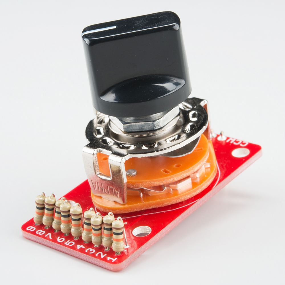
But I've really been thinking about using resistors rather than L-pads. It seems like you could just do something like these below, with the middle resistor value being what you prefer for that driver, then you'd have +/- multiple steps in each direction.
Has anyone done this before?
Another option is to have a switch that could bypass the L-Pad and use 1 resistor that you could install and make it swappable.
The L-Pad just seems like a weak link and source of future issues but a stepped resistor ladder/knob situation could be fixed while still being tunable.
https://www.sparkfun.com/products/13099 - Rotary Switch Potentiometer Breakout
https://www.sparkfun.com/products/13006 - Decade Resistance Box

There are currently 2 users browsing this thread. (0 members and 2 guests)
 Posting Permissions

 Reply With Quote