Hello Earl K
Can you send me coordonate (PM) of the person who buid your horn please.
Regards


Hello Earl K
Can you send me coordonate (PM) of the person who buid your horn please.
Regards
Hi dabass,
These are not my speakers ( horns ) / they belong to John W and he created the horns himself ( on a lathe ) . John W is a member here .
<> Earl K
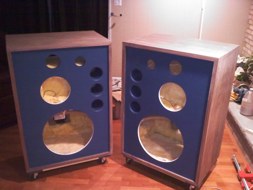
Just got done veneering (and being the first time I have every veneered), I am very happy with the results.
I cannot thank Saeman enough for posting the very helping veneering tips that he did.
I have a few questions about getting the right factory finish now:
1) In regards to sanding the encolsure, do you guys typically proceeds with 200 grit, 400 grit, and finish off with some steel wool?
2) How can I obtain a finish that is as light as possible. I had previously applied boiled linseed oil on my Klipschorns and they have become very dark over the years. Any recommendations for the type of finish I should apply? oil? poly? Again, the goal is to keep the speaker finish as light as possible.
3) What type of router bit is used to bevel the front trim of the enclosure. My DIY 4345 build has a solid walnut molding which is 1" wide and 1/2" thick/deep.
Lastly, I still can't decide whether I should wait for 4313B's new crossovers for the 4345 (especially given the fact that I too will be using a 2" driver), or go ahead and proceed with the latest ones. I have all the parts on hand for the latest ones, but part-express is willing to accept returns with 45 days of purchase date.
Please find below a picture (taken with my cellphone) of the current state of my DIY 4345:
Your enclosures look nice.I took some measurements tonight of another stock 4345 network and hope to have something worked up in a few days.Originally Posted by dkalsi


The front bevel is cut at 60 degrees using a standad bit that is available - 1/2" shank only. If I understand you correctly, your trim is 1/2" thick - meaning the baffle is recessed 1/2" in from the trim front edge. If so you will not be able to exactly duplicate JBL's front trim profile. The factory 4345 baffle is recessed in from the front edge 3/4" to 13/16" and the front remaining flat edge of the trim is approx. 1/8". If you start making successive cuts into the trim to the depth that will yield a face edge of 1/8", you will cut thru the top edge of the trim and into the cabinet substrate. Hope this makes sense.
You have two choices - one is to cut your bevel leaving a 1/4" vertical face remaining - or - stack and glue an additional 1/4" on to the thickness of your face trim. The second option might sound stupid but I think it would be my first choice.
Saeman,
The baffle is recessed 3/4" from the face of the front trip - the 3/4" recess consists of 1/2" walnut trim and 1/4" of MDF (from the side/top that extend beyond the baffle - if that makes sense).
I too used a 60 degree bevel for the trim (1/2" shank).
Thank you and thanks to 4313b for posting regarding the crossover.
I really appreciate all the help I received here at the forums.
Dhar.
Based on the 135 data files I have run over the last few days I would recommend that you prepare to return the 2421B/2425J and 2405 parts. I can't say yet which parts, if any, might be reusable in the new circuit.
Last edited by 4313B; 12-03-2009 at 06:15 PM. Reason: imported correct voltage drive curve
2421B/2307/2308 replaced with 2441/2311/2308.
Stock 3144/3145 network. L-Pad set to 0 (3145).
4313B,
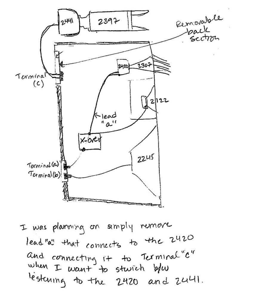
FWIW - I wanted to let you know that I am going to install the 2307+2308+2420 inside my DIY 4345, but will also the 2441+2397 combo which will be placed on top of the speaker.
I was planning on installing two terminal posts at the bottom rear cutout to (a) bi-amp the 2245 and (b) for the upper three components -(2405,2420,and 2122H). I was also planning on installing set of binding posts on the top removable back section of the enclosure. This isolated terminal will then be connected to the 2441 sitting on top of the enclsoure. When I want to use the 2441 instead of the 2420, I can simply remove the back, disconnect the leads to the 2420 and simply attach them to the binding post I installed on the removable back. (See hand drawn picture below).
I have a really stupid question for you - is there any way for you to know whether the new crossovers will work equally well with the standard components (i.e. 2420) as oppose to working well with only the upgraded components (i.e. 2441). I realize that your efforts are to optimize the crossover for the 2441; nonetheless, I am curious how the performace might suffer/benefit when using standard components.
You had previously mentioned that users were already happy with the current schematics when using a 2" driver. Is there any chance that users will also be happy using the new crossovers (which have now been modified for the 2" driver) with the standard 1" driver?
Thanks,
D
The 2420 was never used in the 4344/4345. The drivers used were the 2421B, 2425J and 2426J. JBL didnt make any network changes because those three drivers were supposed to be electrically and acoustically equivalent.
As you can see above in #143 , Greg's statement "won't work" with respect to nilly willy parts swapping holds true. Substituting in the 2441/2311/2308 would require a network re-work.
Now I know that some guys couldn't care less and would do it anyway and post that they like it just fine and that's just the way DIY is. Something like a DEQX could "fix" the issue too.
I wouldn't speculate on how your Smith horns or 2420's would fare.
Ok, it looks like all the parts in the schematic you referenced above for the 2405 are good enough too. The series 6.8 could potentially be replaced by a 6.2 and the parallel 6.8 could potentially be replaced by a 8.2 or 9.1
There is probably more variance between drivers than that though so it might not make any difference.
So it appears just the 2421B passband needs a rework which is what I've suspected for years but never got around to it.
The pink curve below is the stock network measured with an 8 ohm dummy load. The other three curves are the actual stock network measured with a 2421B load and L-Pad set to 0 (note the 4.06 ohm and 17.48 ohm resistors in the models equivalent to an L-Pad set to 0 in a 4345), the stock LEAP model with a 2421B impedance load and the equivalent network LEAP model with a 2421B impedance load.
Yikes! - My mistake. I can swear I remember seeing it somewhere that the 2420 was used in the 4345.
EDIT:
See link: http://audio-database.com/JBL/speaker/4345-e.html
Don't ask me why I decided to look at the above link when I could have easily referenced the documents found here at the forums.
It bet it is nearly impossible to find a 2421B.
I have "fixed" the passband for the 2421B.
The curves of interest below are the dark green and the red curves. The blue curve is from the original schematic you posted in #124 . The bright pink and bright green curves are aquired from measuring the stock network with 8 ohm and 16 ohm dummy loads instead of an actual driver impedance.
Here is the corrected schematic from #124 showing the minimum number of parts you would need to change. This should get you really close.
I will post the complete new equivalent filter in my DIY 4345/4345 Mk II thread along with the fix for a 2441. Naturally I will have to build this and listen to it myself before I truly accept it.
2420 core with a D16R2421 diaphragm.
There are currently 1 users browsing this thread. (0 members and 1 guests)
 Posting Permissions

 Reply With Quote