Yes, JBL cross them at 890Hz in the SAM system...Originally Posted by fpitas

I will probably end up with a LR8 acoustical crossover, depending on the smoothness of the horizontal off axis response.
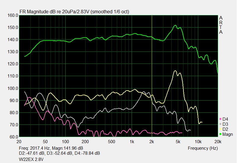
Examining the response curves it looks like the breakup are not as severe (lower Q and gain) in the JBL Aluminum as in the SEAS magnesium you are using, so I have hope.
(I think the JBL are using CMMD cones)
The paper cone are much more forgiving when it comes to breakups, especially when additional damping is used (aquaplass), and JBL typically cross them less than one octave below their breakup peaks (1500AL, etc.)...

 Reply With Quote
 )
)