Nice! Where do you get those circuit boards?Originally Posted by JBLPRO


Nice! Where do you get those circuit boards?

They green PCB's are available on ebay in various sizes. All the circuit wiring is under each network with the exception of the 2202/2441 1.2 kHz network which is wired on the main board.(largest coil & Caps) It was a logical & organized layout keeping each network separate, easier for troubleshooting as well. Also the coils were attached with cable ties and hot glue to prevent vibration. ALL caps were all hot glued into place as well. I used 1/2" standoffs and necessary hardware to elevate the smaller PCB's on the main board. I can send you some links for the vendors if you like. I did not go over the top with really expensive caps and coils. I used the Solen caps and Jantzen Superes resistors parts because all the correct values were available. In addition because I was using a charge couple design I felt it not necessary to use the very best boutique caps. I could have easily double or tripled the cost if I went in that direction.

If you ever decide to produce these please put me on the list.. name you price...looks amazing.
cheers!
I assume you are using these for a pair of 4355's? And.... Would you like to use the same components I used or upgrade? When I know that I can PM you with a quote.
Thanks for your interest.
mk
I used to build networks for people back in the day when I had time. Those days are long gone. Sorry.
actually my speakers are the L300's. I would like to be able to bi-amp them or at least update the crossovers.
forgot that these were for the 4355's.
regards.
Some nice nice work here, absolutely beautiful
But I have never been unable to understand the high count and the many builders (not just here at Lansing Heritage) who use CRIMP type connectors on these otherwise beautiful constructions?
There is no way in hell I'm going to go to those lengths and costs to only turn around and tie it all together with the worse thing that's ever come down the pipe since the 3M Scotchlok..............or these:

I ask myself the same thing every time I have to get a standard slotted screwdriver out of the tool box... "What total dumbass would ever design a screw with a single straight slot..."
Fortunately Phillips had his head on straight. (The credited inventor of the Phillips screw was John P. Thompson.)
I have to say that I don't see a problem with the crimp connectors that have the wires soldered in.
I concur, 99.9999% of the time
Nor do I


"I have to say that I don't see a problem with the crimp connectors that have the wires soldered in"
If used properly, they work well and reliably. The uninsulated variety often can benefit from a bit of solder
as kind of a backup.
Problem is almost no one bothers to use the right tool or match up the wire gauge or cut back the proper
amount of insulator or use decent quality connectors or ...
So in general, I'd advise trying to avoid them unless required (such as interfacing to a driver with spade
lugs as the connector type).
If done right, you'll break the wire before it gets pulled out of the crimp.

Yup. I had a tug of war with the guys at our off road shop with a 10WR vise grip locked on a #10 blue T&B ring end crimped to about six feet of #14 aircraft wire.
Thats a demo they will never forget. When I say pull test I mean PULL!!!
Barry.
If we knew what the hell we were doing, we wouldn't call it research would we.
I trim back properly and have the correct tools for the terminals I have used.................
The main focus of my complaints/dislike for them is related more to corrosion and oxidation than anything else (over the long haul)
Connections that "look" clean and perfectly fine but ain't happenin'................it's never been a strength issue for me, rather a circuit integrity/conductivity one
My other issues (when I really learned to dislike them as a general rule) was back when I was doing a lot of custom audio installs in automobiles
LOTS of problems with faulty connections over time, especially with fly leads, bundles and looms run under carpets
With things using Fastons (like LE25s)? Where I have little if any choice?
Ah well, but I definitely lather up those joints well with DeOxit or similar once they're pushed in place!
I'll solder all the terminations I can until they make it impossible (as it is already almost illegal now!)

HI,
I wouldn't mind a quote for a set of charge coupled crossovers either for the jbl 4355's or 4345's.
thanks
John
JBL 4355 | JBL 4351 | JBL 4425 x 2 | JBL XPL 200 | JBL XPL 160 | JBL 4345
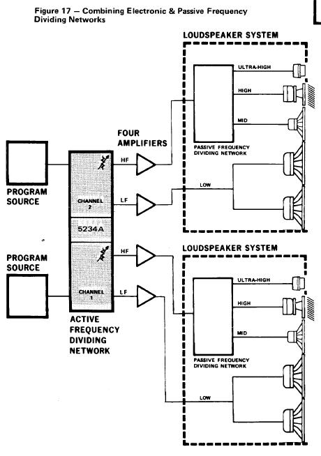
Hi, I'm planning to order parts from Solen.ca and build this xover for my 4344 (schematic attached) but then I just realize that there is no Low Frequency. Could anyone help explain where I would hook my bass driver to ? Thanks.

The filter you show here is for active only.
You need an electronic crossover and two stereo amplifiers.
43XX (2235-2123-2450-2405-CC 3155)5235-4412-4406-4401-L250-18Ti-L40-S109 Aquarius lV-C38 (030) 305P MkII
There are currently 2 users browsing this thread. (0 members and 2 guests)
 Posting Permissions

 Reply With Quote