Hi
- You could, though this is more of kludged-togther solution than I'd like to see . ( I'd also like to see a schematic of the Altec network before commenting much more. ) I also wonder about how the 802-8G will respond to the chosen lowpass point of the 3106 . Hopefully you'll measure the final response of this setup .
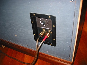
- Using these two crossovers together means I would bypass ( or maybe reuse & move to the 3106 ) the Variable 8 ohm Lpad found in the N801s' HF output section. I would then (re)install an 8 ohm variable Lpad in the new location I've shown in the graphic .
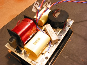
- That 20 ohm conjugate resistor on the horn section ( in the modified 3106) should be considered optional . The value might need to change ( upwards in my experience with Altec 288-8Ks ). My personal sonic preference is not to have any load resistor in that position when using Altec compression drivers .
OTOH ; I find these resistors quite useful when listening to JBL compression drivers .
- With this setup, you're on your own to find the best individual polarities / to accomplish the best phase transitions for your chosen drivers and network(s) .

regards


 Reply With Quote