This is really a weird design, it goes against every fiber of my body screaming "Comb filtering!"Originally Posted by RMC


This is really a weird design, it goes against every fiber of my body screaming "Comb filtering!"
My avatar: 4520 loaded with 2225H on E140 frames,
1x 2202H on custom front loaded horn, 2x 2426 on 2370.

Weird? Don't think so, certainly unconventional compared to others. That said JBL doesn't have the monopoly on knowledge and designs. There's some advanced and patented electronic processing involved in the OWL system.
Can't reproduce Eargle's sketch and technical explanations about the system being copyrighted stuff. However,
"... a listener located on the primary axis of the system will localize left and right image sources slightly out-board of the loudspeakers, due to phasors created at the ears by the slight spacing between loudspeakers... As a result, the localization comes from two sets of complementary cues, resulting in a fairly large listening "sweet spot".
The Owl loudspeakers are primarily intended for use in postproduction spaces where the listening position of the remix engineer remains fairly consistent." (P. 383)
Different and interesting concept. Wide imaging for a stationary engineer...
Thinking about this some more I'm still not convinced regarding woofer size (e.g. 18") making a difference here or that LF diffraction loss is a thing usually applicable to smaller drivers in narrow baffles (as if they were mostly the only ones). For sure it applies to small woofer/narrow cab but what about other larger combos?
Putting a small woofer in a narrow box or a large woofer in a narrow box basically looks the same issue. For example, an 8" driver in a 10" wide box or an 18" driver in a 20" wide box seems like a similar problem to me.
I don't see this as being a woofer diameter or box size ALONE as an explanation. I think its more a matter of LF driver size VS cab size used (proportion of one to the other).
Putting a smaller woofer in a larger size box is probably where LF diffraction loss might be reduced, assuming cab is not already directly on the floor (2Pi) for example.
Interestingly, the OWL speaker system side panels do appear to make a difference when comparing free field (4 Pi) and half space (2Pi) frequency response data shown on WorthPoint link posted:
"response free field: 62 - 20,000 Hz +/- 2 dB fc reponse in wall: 60 - 20,000 Hz +/- 1.5 dB"
The 2 hz and .5 db differences are probably in the tolerance range. Response is practically the same with quite different mounting, whereas in free field (no boundary) LF response should be down by 6 db and its not. So the side panels on the OWL do appear to make a notable difference.
Have not seen the mounting instructions for the OWL speakers, but i guess these could be side panels in action for free field mounting and panels folded or removed for in-wall installation.
Remains the question of is it worth the work, effort or cost to do the same? I guess its for users to decide based on their own situation.
My additional two cents...
Well, that's what I meant basically, and I just realize now that it's in fact a stereo pair in a monolithic enclosure so it makes more sense.
Cool.
My avatar: 4520 loaded with 2225H on E140 frames,
1x 2202H on custom front loaded horn, 2x 2426 on 2370.
@mortron
Troels Gravesen "The LoudSpeaker"
Troels thread ( which outlines a modern take on the 4345 & the design process for it ) is an excellent read and is highly recommended reading ( home-work ).
Note that he does dry-run "mock-ups" before committing to wood cutting.
Here's Troels Gravesen's measurement of a 2123h on a 30cm x 50 cm baffle ( set in the middle ) ;
Now here's the same 2123h on a larger baffle ( 65cm x 105cm ) > I assume with this larger baffle the JBL 10" was placed in the spot where his preferred 10" was located ;
One can quite easily see the response changes that 2 different baffle sizes ( and driver positioning ) actually make .
Obviously, making response measurements are critical to the whole process.

That is pretty sporty cutting down L250s, but then I am considering the same with L7s. My guilt has been dialed down.
My speakers, my rules, I get it. Your 250s look like they belong that way.

Hello turnitdown
My goodness no! Those are scratch built tops. I used the measurements from the L250 and built those tops from there. Thanks for the compliment in the sense I was close enough you thought I cut up a pair. I would would love to own a pair of stock L250's!
Rob
"I could be arguing in my spare time"
Lots of good responses. Lots of people doing things a little different. This is a fun place to come to.
EarlK... Thanks for the comparison. I have always been aware of Troels The Loudspeaker, and never really bothered to look close enough to appreciate the minor nuances in the mid baffle response, but it makes sense. I keep forgetting he sometimes likes to throw a JBL driver into the mix on some of his projects. He's a very thorough designer. I also like that he shares builds others have done. One did a really cool 2 piece version, and I was pretty impressed, but wondered if it measured the same...
http://www.troelsgravesen.dk/TheLoudspeaker_Tobias.htm
Seeing people on other forums and their experiments with how sound travels around the baffle and sides of the speaker makes me wonder about how the side walls, or lack of would affect response. I can see now how building a kit would be one of those "do it the way it says first, then mess around". I start to think of the Joseph Crowe ES horns where the mouth smoothly transitions to a foam pocket on the back of the horn. This is where having scrambled eggs for brains gets me overwhelmed. Since I know where I'm going with this, I am definitely gonna read Troels research thru different lenses.
*Also* (You made a passing comment to me about something in another forum about a retailer close to us... I'm curious to follow up with you in PM and ask a question if possible).
Turnitdown, those rehoused L7s one member made are pretty hot. They look awesome and can see how you'd be tempted. I almost wanted some L7 in rough condition cabs more than nice L5's I got, so I could also do that. The L series is a bit of a strange one, in that they sound great but look a bit... Subtle? I dunno how to word it. Granted, I would guess they're not supposed to dominate a room visually like some other larger designs. I see the stock enclosure like the B2 stealth mode... Nobody realizes you got some big arse woofers doing the heavy lifting. It'd be a tough call if I had really nice condition original L7.
The OWL speaker looks very cool from an engineering standpoint. "It doesn't look like it should, but it sounds good" is about as good as I can hope for in DIY HAHA. I guess they're pretty closed about their secrets but it reminds me of how Polk Soundbars had that weird out of phase driver on opposite side, I think it was SDS? More than just a long stick with speakers jammed in there, but didn't look like much more. Not that the techs are necessarily comparable, but the experience of something coming from a speaker you expect little from is always pleasant. Having been into open baffles, I can't rule anything out from sounding good and looking weird
And for everyone's benefit, I just ordered a UMIK1 from Cross Spectrum labs last night after a few Root Beers and am pretty excitedI'm going to build a Limp module to measure drivers as well. Combination of frustration in my limits and the guilt of not being able to contribute as well as I could to the technical side of the discussion.
Thanks again for all your posts folks... Means a lot to me. Much appreciated.
This is really a great look ( to these eyes ) of one builders interpretation of Troels "The LoudSpeaker".
I love the contrast of the black face to the natural Baltic Birch sides.
Morton, once you get your test mic then you'll want to see how different baffle sizes effect the low-end response of your 2251j .
- I would think that experimenting with a cardboard false front ( and fake side returns ) would suffice.
Troels has taken the High Efficiency 4-way to a whole new level.
I would recommend copying as much of his design ideas as is possible.
I've already made some modifications to various filters for you to start with ( I'm just waiting for you to get your UMIK-1 so that you can get a more accurate Acoustic Centre for your 2251j > since it's a deeper driver than my 2123H ).
I determined that the Z-OffSet ( between one of my 2123h's and a CDX1-1745.152i combo >> is about 4.2 inches ). The 2251j might be less ( which effects crossover design ).
No need for a different waveguide though, > the 152i clones are at least as good ( performance-wise ) as the 18Sound XT1086 that Troels uses.
IMHO, the crossover design concepts that he's used are a good step-up from the standard 4345 network ( which could use a redesign ).
It's hard to give much love to a response that measures as lumpy as the following;
Troels has done very well at achieving a smooth response ( ignoring the differences in data smoothing ). See;
That's not to say that GT can't//didn't produce similar . See;
If my project, I would explore using a lower crossover point ( between the 18" and 10" ).
- Troels successfully did 200hz > I would try similar > his response graphs of the 2123H ( on his large baffle ) have shown that the 2123 will get down there (& the 2251j measures virtually the same SO; ).
See;
PS;
The retailer that I was referring to is "Q-Components" >> who I'm sure you are familiar with.
- Post your question here ( I rarely do PM's )
So, motivated self-interest has me playing with crossover values ( I own many JBL 10 inchers and happen to also own the same horn/driver combo you have ).
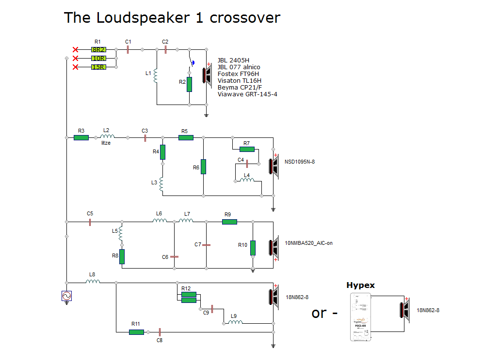
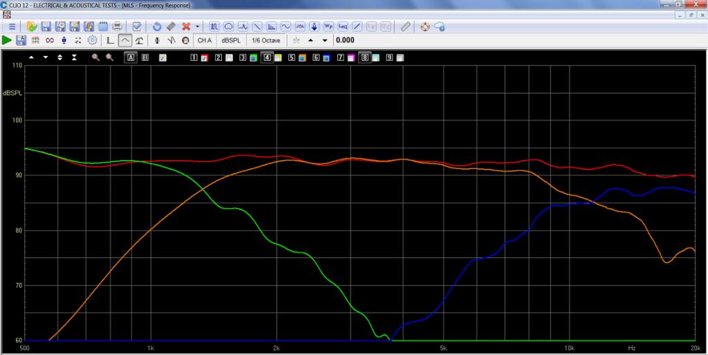
Here's a ( busy ) science fiction graph that shows a bunch of filtered ( as well as raw ) responses for the involved components. Absolute levels are simply guesstimates ( good to within a couple of db ).
The brown trace is a low-passed ( only ) JBL 2251j . The raw response comes from the EDS info pack ( found in this web-sites "Transducer" area ). This is setup for bi-amping ( done by omitting the LC components that make up the HiPass on the 10 incher ) .
The wavy black trace ( filtered ) is one of my 2123h mids ( measured at 2' ) operating within a 0.65 cu' test enclosure ( tuned to 100hz ) . It was hipassed by the regular LC values found in the N3145 ( 60uF + 4.8mH ) .
- The extreme peak at 850hz ( preceded by a trough ) is undoubtedly a diffraction anomaly that would hopefully be mitigated by the use of a very large baffle.
The pink trace ( which is most likely a bit low in its starting level ) is the raw response of a combo CDX1-1745///152i horn ( measured at @ 2' out ).
As previously mentioned, I measured the off-set ( between the two drivers Acoustic Centers ) to be about 4.2" .
- This distance needs to be verified ( empirically ) by building up the network to see if it all hangs together properly ( which is sometime in the future ).
I believe Bi-Amping ( anywhere from 200 to 300hz ) could be the wisest ( + maybe cheapest ) choice for your project ( assuming you've got another amplifier to use ).
@mortron,
So, continuing on with the topic of Baffle Effects ;
Troels ( again ) has nicely shown the ( slightly negative ) effects that can happen when a horn gets mounted into a baffle.
Here we see the traces of his ( two ) freestanding horn/driver combos;
- Very well behaved I must say.
Next we see what happens to the response once the horn//driver combo has been placed in the baffle;
Not so linear now ( the very very mild bumps at 3.3K and 8K have grown some as the almost perfect " beginners ski-slope" has been mis-shapen .
- In contrast, the LF rolloff is now smoother and appears to roll-off at a gentler rate ( at least from what's visible in the pic ).
Here we see Troels solution to the first bump ( the second is simply utilized as part of the lowpass hand off to the tweeter ).
- He has inserted a PEQ cut ( in the form of a series LCR notch placed in parallel with the driver ) .
I anticipate something similar will be needed with your final horn circuit ( once you see the effects of an actual baffle ).
@mortron
Here's a rework of the LC values ( found in the HiPass portion of the previously posted network ).
The rework results in smaller value capacitors which should equal a money savings.
The squiggly purple line represents using my own 2123H with the pictured crossover values ( measured within my small test box at @ 2' >> it's front baffle is 37.5cm x 28.5cm, W x H ).
- The "trough" at 6500hz and the "peak" at 8500hz nicely illustrates some diffraction effects.
The much flatter black line represents this same crossover using Troels Gravesen's 2123h file for the midrange ( as measured on his large baffle >> 65cm x 105cm )
One can clearly see the advantage offered by the large baffle ( for the linearity of the 10" cone drivers ).
Wow EarlK, that is a lot of work. Thank you very much. I am blown away... I don't think I would be able to focus on that long enough to see it through. I bet it also helps to be much more knowledgeable and better equipped too heh. I am working on trying to improve that part.
So much to address, I don't know if I will get it all.
- Bi-Amping would be what I am after. Have a Crown XLS1500, and a Yamaha P2150 for power amps at the moment, and also have a few others but am just using those two for now with my subs and L5 respectively.
- For crossover duties, a Driverack 260 replaced an Ashly XR2000 which I still have as swell. The 260 seemed to be more detailed than the Ashly and wonder if its not in need of some service. Plus the Driverack has EQ, Delay etc. I dunno if it will be necessary or have benefit here?
- I notice Troels and the JBL 4345 don't recess the drivers or horn. I presume your filter is also based on flat mounting them? Are all the QSC clones close enough that the circuit wouldn't change? These are B52's and forget what the consensus was when everyone compared them.
- In the most recent circuit... is C5 obscured or is that a to be determined by me value?
- The one speaker built by a Troels' reader is a very good looking speaker indeed, well thought out, and like the idea of the modular nature of the speaker. Has a unique look and makes practical sense. Normally I would be apprehensive about adapting an existing project, but that builder knew what he wanted and how to do it. Very class.
- Taking the 18 upto 290hz or wherever seems a bit high, but its comforting knowing that GT didn't mind and that it isn't struggling to get to where I need it. I've never had much luck going higher with bass and dropping 200hz would make more sense if at all possible. Todallin in the other thread seems to really favour a 2.5 way approach to the low end of the 2251J. I guess once I get a baffle I will have to see how low the 2251J will actually go.
*** In regards to Q, you mentioned a bait and switch in said comment, and wondered if that was a personal experience, general reputation or what? I ended up buying drivers they didn't have in stock, and waited for the shipment a little before cancelling my order. Is that common??
Last edited by mortron; 09-13-2021 at 03:03 PM. Reason: touchups
Hi,
"C5" is out-of-circuit // not used . When one sees a part that has no value that means it's open circuit. If one sees a part with a line through it ( + no value ) then that means it's a short circuit /"piece of wire" .
Regarding "Q-Components". Really, I can't remember the context for that comment . I don't think that they've ever pulled a "bait & switch" on me personally.
I would move the crossover point down to 200hz and then just give it a listen ( since it's easy to do with an electronic crossover ).
All 3 of those horns ( the original QSC 152i and the 2 clones ) are close enough for the purposes of spit-ballin passive crossovers.
One needs to take any simulation // build it // listen to it // then make the necessary changes to it that personalizes it and finesses it.
Even the best simulation is really just a starting point.
The short answer is no. But the devil is always in the detail with actual physical construction of the loudspeaker from a paper design.
The baffle dimensions of the 4345 were defined by the layout of the drivers on the baffle, the woofer diameter and the gross enclosure volume.
To assist in your questions have you considered the alternative dimensions of the 2245 for an enclosure below your mid high frequency array?
If you looking at a separate woofer enclosure the internal dimensions might look like 58cm Hx 70cm W x 55cm D. You could make the woofer enclosure 70cm deep of you have sufficient room behind the enclosure front baffle.
To answer your question on baffle step compensation this is mostly used in single 6 1/2 - 8.00 inch woofer tower designs. The narrow front baffle significantly limits the the floor boundary reflection off the baffle surface defined by x, y dimensions causing an approximate -6 db reduction in SPL below a defined frequency.
Some engineers use a helper woofer below the main woofer to back fill the loss of level with a damped 6 db low pass filter at a defined frequency.
In your separate enclosure approach you dont need to worry about the woofer BSC as its in very close proximity to the floor boundary and at frequencies below the crossover point they are largely omnidirectional. That is the baffle is no longer acting as a reflector like it is at higher mid frequencies.
This is because those frequencies are quite large compared to the woofer baffle dimensions x,y.
In comparison the narrow baffle tower design has the mid bass woofer a considerable distance from the floor boundary and baffle becomes less effective at reflection of frequencies defined by the baffle x, y.
What you will need to assess is the potential for cancellation of the lower end of the cone midrange at a frequency equal to the circumference of the midrange enclosure. If the enclosure was a cube shape and suspended you may see cancellation at a defined frequency.
However, if you arrange a narrow rectangular mid/HF Array baffle and mount this enclosure flush with the woofer enclosure it should not be a significant problem. For example a 30cm x 75cm x 25cm. The actual internal dimensions of the mid to be need to be assessed based on the desired LF response of the mid cone. You could use a sono tube to simplify construction, a wedge shaped enclosure or a non equal side rectangular enclosure.
I hope this brings some clarity to your original question
In summary think about the woofer enclosure profile and how you wish to scale the dimensions.
The work out your baffle dimensions for the mid/high frequency array based on driver baffle cut out dimensions and driver locations. I think this is an interesting project. If you need any help send me a pm.
Ian
There are currently 1 users browsing this thread. (0 members and 1 guests)
 Posting Permissions

 Reply With Quote