Results 1 to 10 of 10

Thread: Can Someone Explain the Apparent Logical Inconsistencies of the JBL Tapped Inductor?

  1. #1
    Senior Member
    Join Date
    Jul 2003
    Location
    Orange County, CA
    Posts
    3,603

    Can Someone Explain the Apparent Logical Inconsistencies of the JBL Tapped Inductor?

    I have a pair of 3115 crossovers that use a tapped inductor. The schematic shows the inductor to be 3.85 mH across the blue and black, with three taps, red, white and green, along the way.

    I opened the crossover and cut the blue and black leads away from the circuit so I could measure the inductances. The R/W/G go directly to the HF +, so nowhere with no speaker and are disconnected.

    With one probe on the blue wire, I read 0.90mH to the red, 1.29 mH to the white, 1.78 mH to the green and 3.63 mH to the black. The black should be the 3.85 mH and 6% is within tolerances. No problem.

    OK, now the fun starts!

    I would think that if I put a probe on black and a probe on green the value should be 1.85 mH (i.e., 3.63 - 1.78), but is 0.35 mH

    Black to white should be 2.34 (i.e., 3.63 - 1.29), but is 0.63 mH.

    Black to red should be 2.73 mH (i.e., 3.63 - 0.90), but is 0.98 mH.

    And...,

    Red to white should be 0.39 mH (i.e., 1.29 - 0.90), but is 0.06 mH

    Red to green should be 0.88 mH (i.e., 1.78 - 0.90), but is 0.17 mH

    White to green should be 0.49 mH (i.e., 1.78 - 1.29), but is 0.03 mH

    http://www.jblproservice.com/pdf/Net...%20Network.pdf

  2. #2
    Senior Member
    Join Date
    Jul 2003
    Location
    Orange County, CA
    Posts
    3,603
    Think I figured it out.

    It would make sense that the blue wire is closest to the core and each successive tap gets further away with the black wire being the outtermost feed. With less influence from the core, the windings produce fewer mH per turn, though the number of turns may or may not be consistent between the various taps.

    So for example if each tap consisted of 20 windings, the 20 windings between the core and first tap would produce more mH than the 20 windings between the last tap and outter feed.


  3. #3
    Senior Member turnitdown's Avatar
    Join Date
    Jun 2014
    Location
    Tallahassee, FL
    Posts
    260

    Hmmm

    What happens to the DCR and is it consistent/predictable?

  4. #4
    Senior Member ivica's Avatar
    Join Date
    Jan 2008
    Location
    serbia
    Posts
    1,703
    Quote Originally Posted by toddalin View Post
    Think I figured it out.

    It would make sense that the blue wire is closest to the core and each successive tap gets further away with the black wire being the outtermost feed. With less influence from the core, the windings produce fewer mH per turn, though the number of turns may or may not be consistent between the various taps.

    So for example if each tap consisted of 20 windings, the 20 windings between the core and first tap would produce more mH than the 20 windings between the last tap and outter feed.


    Hi Tod,

    From the attached fro,ul for air-core multilayered coil it can be seen that all coil dimension have influence in its inductance.
    So for iron-core coils I can imagine that it would be the case too, but the core dimensions would have an influence too.

    http://www.electronics-tutorials.ws/...nductance.html

    http://www.66pacific.com/calculators...alculator.aspx


    regards
    ivica
    Attached Images Attached Images  

  5. #5
    Senior Member
    Join Date
    May 2007
    Location
    Ingolstadt in Germany
    Posts
    456

    How did you measure the inductances?

    What kind of measurement gear did you use?

    Ruediger

  6. #6
    Junior Member
    Join Date
    Oct 2017
    Location
    Thunder Bay Canada
    Posts
    2
    What you measure seems normal. I don't know the exact science behind it but I have wound enough inductors to know that inductance doesn't increase linearly with number of turns or wire length.

    ie it does not require twice the wire length to wind a 2mh inductor as it does a 1 mh. It requires much less, so if you wound a 2mh inductor tapped at 1mh you would find the second half has much less windings and would not read near 1mh on its own.

  7. #7
    Senior Member
    Join Date
    Jul 2003
    Location
    Orange County, CA
    Posts
    3,603
    Quote Originally Posted by Ruediger View Post
    What kind of measurement gear did you use?

    Ruediger
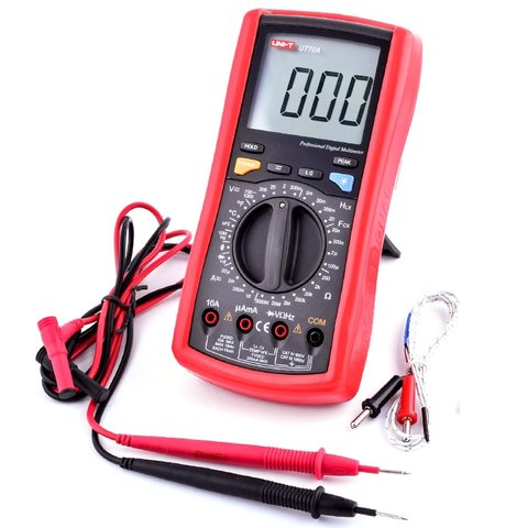
    Multimeter with inductance. (Uni-T UT70A)

  8. #8

  9. #9
    Senior Member ivica's Avatar
    Join Date
    Jan 2008
    Location
    serbia
    Posts
    1,703
    Quote Originally Posted by mmaki View Post
    What you measure seems normal. I don't know the exact science behind it but I have wound enough inductors to know that inductance doesn't increase linearly with number of turns or wire length.

    ie it does not require twice the wire length to wind a 2mh inductor as it does a 1 mh. It requires much less, so if you wound a 2mh inductor tapped at 1mh you would find the second half has much less windings and would not read near 1mh on its own.
    Hi mmaki,

    L=k*N*N, where N is the number of turns

    regards
    ivica

  10. #10
    Senior Member
    Join Date
    Jul 2003
    Location
    Orange County, CA
    Posts
    3,603

    2 + 2 +2 = 6..., or is it 8???

    Here is an interesting observation.

    I ordered six, 16 gauge, 2.0 mH inductors for the woofer. A single order 6.0 mH inductor would cross the 2241s over at 210 Hz.

    When the three coils are connected, they produce 6.0 mH. But stack the three together, and you've got to get them near perfectly aligned, and they total 8.0 mH bringing the crossover point down to 160 Hz.

Thread Information

Users Browsing this Thread

There are currently 1 users browsing this thread. (0 members and 1 guests)

Similar Threads

  1. The next logical step from my UREI 813
    By Herman Chigrin in forum Lansing Product General Information
    Replies: 16
    Last Post: 12-23-2017, 10:19 PM
  2. Alternative to tapped inductor in 3110a or 3115a?
    By robfive in forum Lansing Product DIY Forum
    Replies: 56
    Last Post: 05-21-2014, 05:15 PM
  3. L100T3 Crossover Inductor DCR Values and General Inductor Advice
    By Wayniac in forum Lansing Product DIY Forum
    Replies: 4
    Last Post: 12-10-2012, 12:15 PM
  4. Crown PSA-2XH Fan Coming On for No Apparent Reason
    By toddalin in forum Lansing Product Technical Help
    Replies: 2
    Last Post: 08-22-2011, 06:07 PM
  5. Tapped Chokes
    By speakerdave in forum Lansing Product Technical Help
    Replies: 4
    Last Post: 01-02-2006, 12:40 PM

Posting Permissions

  • You may not post new threads
  • You may not post replies
  • You may not post attachments
  • You may not edit your posts
  •