Hi Gary,
Some
Reading at Hostboard from Todd.
From his dissertation it appears that "L2" was the positive polarity ( giving a compression wave when a positive signal is applied ) for the older style compression drivers.
The basic problem would appear to be that Altec swapped the physical orientation ( looking at a back-cap, going left to right, with the 2 terminals at 12-o'clock ) of where
"+" physically occurs ( when they went from old style to the new style back-cap ).
- ie; It's now on the left, instead of being on the right .
I would just swap the wires going to the HF drivers ( from where you currently have them ).

PS; I typically check all my connections with an electronic polarity checker so that I know what's actually what ( when it comes to positive & negative compression waves > though that doesn't really help you here ) .
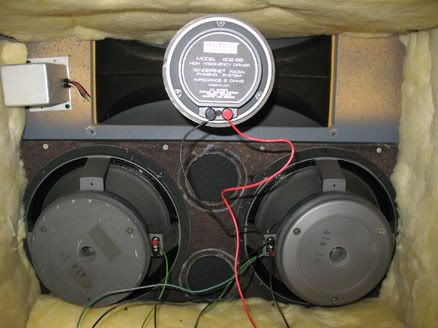
PS#2; The bottom two pics I previously posted are of Skywaves 9844 system and were taken when he was messing about with different crossovers ( you can see the original crossover is out-of-circuit in the top left , inside the box ).


 Reply With Quote