Page 1 of 2 12 LastLast
Results 1 to 15 of 23

Thread: Simulating 5235 Active Crossover Filter Cards

  1. #1
    Junior Member
    Join Date
    Feb 2017
    Location
    Phoenix, AZ
    Posts
    17

    Simulating 5235 Active Crossover Filter Cards

    Hello all,

    I know there has been some work done in the past on figuring out the schematics and component values for these cards. I thought I'd see if anyone had any pointers / advice on setting up a simulation bench for these filters, source / load impedance, connections, etc. Planning to have a look at the 5235 schematics for hints, but hoping someone here has already figured it out

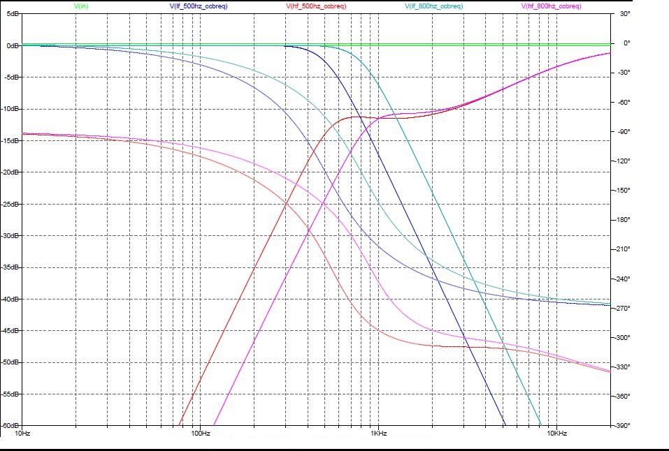
    I'm interested in reproducing the sims for the 500Hz 18dB CCBREQ, and then looking at some custom options and including the active crossovers in a larger system simulation. Here's what I'm working on:
    http://www.audioheritage.org/vbullet...799#post403799

    Some of the related threads I've come across:
    4355 card schematics: http://www.audioheritage.org/vbullet...-card-for-5235
    Schematic reverse eng for FF/CC cards: http://www.audioheritage.org/vbullet...ghlight=CCBREQ
    Info on 24dB active card: http://www.audioheritage.org/vbullet...-cards-to-swap
    Manual/Schem for 24dB active card: http://www.audioheritage.org/vbullet...card-schematic
    discussion of over options: http://www.audioheritage.org/vbullet...nsation-primer

    Thanks,
    Rob

  2. #2
    Junior Member
    Join Date
    Feb 2017
    Location
    Phoenix, AZ
    Posts
    17
    Also an extensive consolidation of information here, translated from a french forum:
    https://translate.google.com/transla...35&prev=search

  3. #3
    Junior Member
    Join Date
    Feb 2017
    Location
    Phoenix, AZ
    Posts
    17
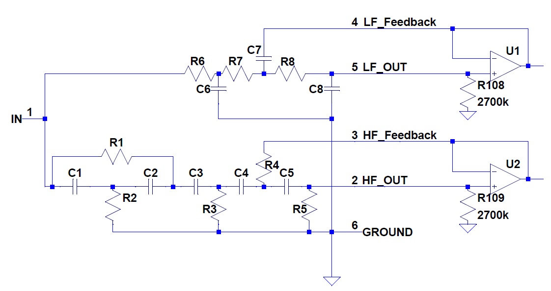
    This image of the CCBREQ schematic from the french thread above seems to have answered my question, and should let me get started....


    I should seriously print that whole thread to pdf in case it ever goes away. Crazy amount of info in there.

  4. #4
    Senior Member berga12's Avatar
    Join Date
    Jan 2016
    Location
    Italy
    Posts
    221
    I can confirm you that schematics are correct, I used them to modify my EEQ card into a normal 18db so no problems.

    you can also build the PCB by your own with "home made" tecnique (stencyl or pencil and acid) or simple multi-hole board and hand soldering.

    I just don't know "connector code".

  5. #5
    Senior Member
    Join Date
    Apr 2014
    Location
    Europa Union
    Posts
    130
    Quote Originally Posted by miscrms View Post
    This image of the CCBREQ schematic from the french thread above seems to have answered my question, and should let me get started....


    I should seriously print that whole thread to pdf in case it ever goes away. Crazy amount of info in there.
    It took me a while to write all of this. I still have plans to translate it, one day, when I'll have time. Just ask if there is something difficult to understand from
    automatic translation.

    Note: I just checked the begining of the automatic translation. Should be much better if I do it by myself.

  6. #6
    Junior Member
    Join Date
    Feb 2017
    Location
    Phoenix, AZ
    Posts
    17
    Thanks dn92, there is an amazing amount of info collected there. Even with the google translation its a great resource!

    PS if you are still willing to share your board layout files I would love to have a look! Sent you a PM.

    One way or another I'm going to need to make some custom cards, most likely either a full 2360/2404 crossover ~10kHz or at least LP for the 2360 to match a passive 2404. I'm also mightily intrigued by the delay sections in the 5333. I don't think its very feasible to get the driver on a 2360 physically in the same plane as the 4648A, so I've been thinking about trying to add some delay on the LF....

  7. #7
    Junior Member
    Join Date
    Feb 2017
    Location
    Phoenix, AZ
    Posts
    17
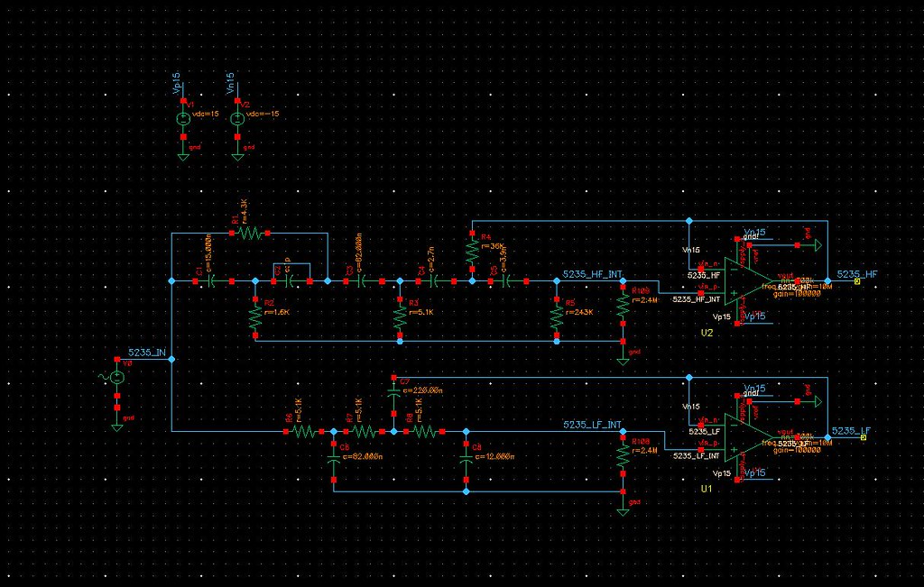
    With the help of the schematic above I was able to simulate the 500CC card as follows:


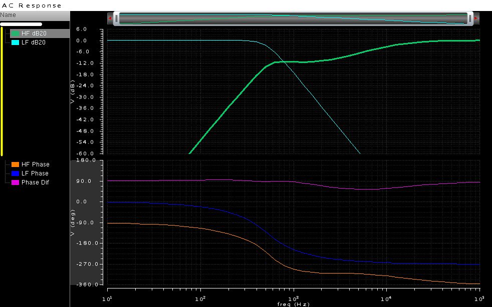
    Frequency/phase response looks about right:


    With that I'll take things back to my main thread as I explore system specific options:
    http://www.audioheritage.org/vbullet...799#post403799

  8. #8
    Senior Member
    Join Date
    Apr 2014
    Location
    Europa Union
    Posts
    130


    berga and miscrms, pcb files (freeware version of Eagle) are in your email boxes.

    In addition I've LT Spice simulation files available.

    The delay required to align 2360 is an issue. In 5333 and other types of JBL crossover board (I think ref M12), but also in M552/553 there are delay values mentionned in the documentation, a bit more than 1ms if I remember well.
    It is possible to design a specific active board, with delay section as there are three additional pins on the connextor that are providing power supply.

    6 pins and 9 pins connectors are availble at Mouser.

    To handle such type of delay (but inferior in value) for my TAD 2402 clones, I use one 5235 per loudspeaker, with dual 18dB Butterworth crossover (to form a 36dB/oct LR crossover) and a 12dB Butterworth for HF with EQ (there is only one EQ in the original TAD TN-1/TN-2/TN-3 passive crossovers).

    If you want to go that way you shall do measurements as well as simulations of the crossover.

    Another approach that will be easier is to move to a digital crossover.

  9. #9
    Senior Member
    Join Date
    Apr 2014
    Location
    Europa Union
    Posts
    130
    Quote Originally Posted by berga12 View Post
    I can confirm you that schematics are correct, I used them to modify my EEQ card into a normal 18db so no problems.

    you can also build the PCB by your own with "home made" tecnique (stencyl or pencil and acid) or simple multi-hole board and hand soldering.

    I just don't know "connector code".

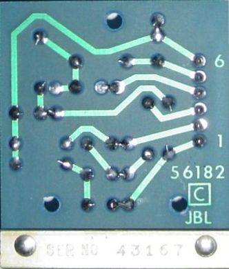
    Pin 1 is the pin closer to the front plate when board is installed in the 5235, it is written on the original PCB.


  10. #10
    Junior Member
    Join Date
    Feb 2017
    Location
    Phoenix, AZ
    Posts
    17
    Interesting, thanks. Look forward to looking over the board files.

    I'm slowly working up to trying to simulate my whole system chain (at least from the pre/pro output on), which is sort of the focus of the other thread. I have an HP 4192A Impedance Analyzer I'm planning to use to make impedance measurements of my drivers. And an HP 35665A Dynamic Signal Analyzer for characterizing frequency response and phase/delay of Amps and filters. Lastly I have a calibrated UMIK-1 and iOS Audiotools which I'm hoping to use for the final transfer function / phase of the drivers. If that won't cut it I'll probably try and find a way to get a calibrated mic input into the 35665A.

    I don't know how much it really matters in my cobbled together system, but I've gotten quite interested in time/phase alignment so it will be an interesting project

    Rob

  11. #11
    Junior Member
    Join Date
    Feb 2017
    Location
    Phoenix, AZ
    Posts
    17
    Yeah, I'm sure a digital crossover would be easier. But what can I say, I'm an analog/RF guy. DSPs seem like cheating somehow At this point the project is as much for curiosity sake as anything.

    Rob

  12. #12
    Senior Member
    Join Date
    Apr 2014
    Location
    Europa Union
    Posts
    130
    Quote Originally Posted by miscrms View Post
    Interesting, thanks. Look forward to looking over the board files.

    I'm slowly working up to trying to simulate my whole system chain (at least from the pre/pro output on), which is sort of the focus of the other thread. I have an HP 4192A Impedance Analyzer I'm planning to use to make impedance measurements of my drivers. And an HP 35665A Dynamic Signal Analyzer for characterizing frequency response and phase/delay of Amps and filters. Lastly I have a calibrated UMIK-1 and iOS Audiotools which I'm hoping to use for the final transfer function / phase of the drivers. If that won't cut it I'll probably try and find a way to get a calibrated mic input into the 35665A.

    I don't know how much it really matters in my cobbled together system, but I've gotten quite interested in time/phase alignment so it will be an interesting project

    Rob
    Dear Rob,

    You should already have received them by email.
    As a starting point use the CCBREQ board, and do acoustic measurements, for learning and understanding. From this you'll be able to do experiments.

  13. #13
    Senior Member
    Join Date
    Apr 2014
    Location
    Europa Union
    Posts
    130
    For large CD horns, JBL in IM12 crossover board applied 1.9ms (http://www.jblproservice.com/pdf/MPA...ules/IM-12.pdf). This delay is quite logic regarding the Horn depth.
    Smaller delay (0.7 ms) is for JBL 238x horns

    In JBL 53-5333 documentation, default delay values are set to 0.35 and 0.7 ms, despite this board is for 236x horns. http://www.audioheritage.org/vbullet...3&d=1200019798
    53-5334 was the JBL 5235 24dB/oct crossover board for 238x horns.

    In this italian JBL catalog, 53-5333 is mentionned being for 238x and 53-5334 for 236x: http://www.cieri.net/Documenti/Catal...0(1992-03).pdf

    There is no available documentation, and then it is not possible to check if there has been an inversion between 53-5333 and 53-5334 documentations.

  14. #14
    Junior Member
    Join Date
    Feb 2017
    Location
    Phoenix, AZ
    Posts
    17
    It may depend on the specific mount and horn I suppose. I'm using the 2506B mount on the 4648A w/2365A horn, which puts the CD (very) roughly 19" behind the woofer voice coils. I'll need to do real measurement of course, but I believe that would put the required delay at ~1.4ms for my setup. There are notes in the 5333 manual for changing the caps to make the delay shorter by a factor of 10. It would be interesting to see how far they could be pushed the other way before running into issues. A factor of 2 might be feasible?

    One problem with delaying the LF to match the HF plane is then the UHF driver (2404) would also need to be at the HF CD plane. I haven't figured out a way to do this without having the UHF driver significantly obscured by the horn or very far away from the other drivers.

    Rob

  15. #15
    Junior Member
    Join Date
    Feb 2017
    Location
    Phoenix, AZ
    Posts
    17
    I haven't used them yet, but have looked at this board prototyping source several times.

    https://www.expresspcb.com/miniboard-standard/

    This particular offering might be convenient as it is their cheapest, but the size is constrained to 2.5" x 3.8". Conveniently the 5235 cards I have measure 2.5" x 2.25", so they do have a dimension in common. The 3.8" might work as is for a somewhat expanded card, a 2.25" board with a wasted crust or two 1.9" slightly squeezed cards. $41 + shipping for qty 3 (no additional fixed setup NRE) seems pretty good for a two layer board with 1 business day turn.

    For $61 you can get the same boards with solder mask and silkscreen.
    https://www.expresspcb.com/miniboard-pro/

    For better or worse you do have to use their free / proprietary design tool.

Thread Information

Users Browsing this Thread

There are currently 1 users browsing this thread. (0 members and 1 guests)

Similar Threads

  1. 5235 18dB Filter Cards
    By jblbgw_man in forum Lansing Product Technical Help
    Replies: 3
    Last Post: 11-09-2007, 07:51 AM

Posting Permissions

  • You may not post new threads
  • You may not post replies
  • You may not post attachments
  • You may not edit your posts
  •