I was kicking around the idea of building one of these for a 4345 DIY project. But where in the world would one find 5.4 and 4.8 mH iron core inductors?


I was kicking around the idea of building one of these for a 4345 DIY project. But where in the world would one find 5.4 and 4.8 mH iron core inductors?
Parts Express has 5.5 and 4.7 iron cores, just the first place I looked.
You could bi-amp them and do away with the larger coil (is it 5.5 or 6.4? I can't tell for sure).
Edit: I blew it up and that bigger one is 6.4mH

You can also get bigger and unwind it.
Always fun learning more.......
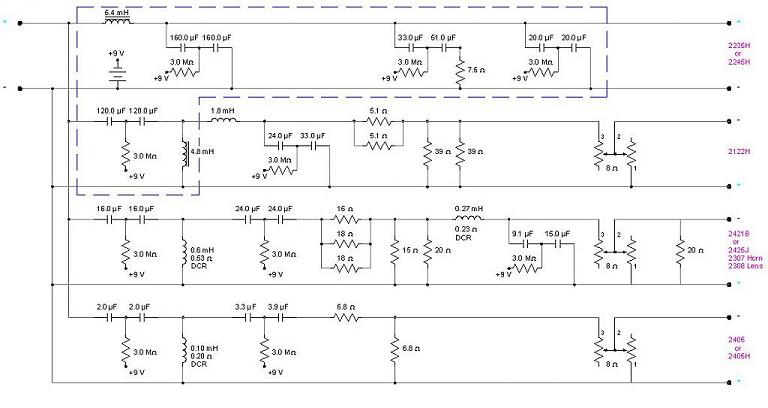
I should have been more clear in my original post. Parts Express was the first place I looked at before I posted and like you said they have 5.5 and 4.7 mH. But the schematic (it's a little fuzzy) states 5.4 and 4.8 mH. Close, but no cigar. Just thought with the many, many posts about this particular crossover someone hopefully knows where to get them. Thanks.Originally Posted by JeffW

Tom

If you can't find a coil with the required inductance value then order a coil with a slightly higher inductance value and then remove a few windings from it. But, it will require you to have an inductance meter.
Fortunately, the cost of Digital LCR Multimeters has come down a lot.
A quick source on amazon turned up the following for under $40.00:
"MASTECH MS8269 Handheld Digital Multimeter LCR Meter Resistance Capacitance Inductance & Temperature Tester"
And if you question the accurately of such a cheap LCR meter than you can always calibrate it by taking a reading of a coil before you remove any windings from it.
And if you have no long term need of a LCR meter then you can always sell it after the 3145 networks are built.
I would think that you could find a buyer for slightly used LCR meter right here on this site.
Baron030
I still think it says 6.4, but that's just my opinion. And there's just 2% difference between 5.5 and 5.4, likely much closer than the tolerance of the capacitors.
Edit:
OK, here's his post with the list, I stand corrected, 5.4 it is:
http://www.audioheritage.org/vbullet...l=1#post324116
Here's a repost ( from Heather ) of Giskard's original BOM ( for the 3145 ).
Looks like she got 5.4, as well. That schematic sure has a 6 looking 5 in it.

Better readable here?

43XX (2235-2123-2450-2405-CC 3155)5235-4412-4406-4401-L250-18Ti-L40-S109 Aquarius lV-C38 (030) 305P MkII
I swear that still looks like a 6 to me, but the 5.1 ohm resistors are clearly 5s. Anyway, I'm pretty sure I was mistaken and 5.4mH is the correct value. I won't hazard a guess on why the parts numbers in the BOM above are 5.6mH, I ain't building them, anyway (and I'd still bi-amp that inductor out of the system, to boot).
Not 5.4mH, not iron core, not sure.
L125.6 http://solen.ca/products/inductors/l...1-93mm/l125-6/
S125.6 http://solen.ca/products/inductors/s...2-05mm/s125-6/
S145.6 http://solen.ca/products/inductors/s...1-63mm/s145-6/ Has the same .63 DCR as the L125.6
The first line of parts numbers ( in Giskards BOM ) are from Solen, see ; Solen S145-6.
That first L125-6 entry equates to Litz Wire, 12Ga, 5.6mH ( .63 DCR ) .
Both coil types would need to be unwound to get the correct 5.4mH value .
PS; now you got it Jeff!
Thanks. That's a good point. I do plan to bi-amp. For some reason I was not thinking straight when I was glancing at the schematic. I was just thinking the top section was HF, the middle was MF and the bottom section was LF.However, I sure wish I could hear from someone that actually built one of these as to the verified values, sources, etc. and any helpful tips and tricks. Thanks.
Tom
OK I've been studying the old posts http://www.audioheritage.org/vbullet...upgrade/page14 and http://www.audioheritage.org/vbullet...-modifications for several days now. These are excruciating detailed and drawn out communications over a long period of time back in 2005 between mainly a French guy in Canada (BandKMan) and others mostly (Ian Mackenzie) and others about crossovers for 434x systems with 4313B. I am enlightened and much more informed after reading these strings. I also think I now better understand 4313B's reaction to my post last year questioning Charge Coupled Crossover Networks. Sorry I stumbled into this about 10 or more years after the fact! But I am not a troll. I was and still am an innocent and honest bystander at the wrong place at the wrong time when I questioned Charge-coupled crossovers.
It seems obvious to me from reading all this is that the way to go on a 4345 DIY crossover is the bi-amp option. My problem is I'm from the old school of what electronics were back in the 1960's. I studied and was well versed with all the Capacitor/Inductor stuff back then, but my career path led me in an entirely different direction (Air Traffic Control and Law Enforcement). Other than the Nelson Pass crossovers I built for my L300s last year, I haven't fooled with this stuff since the late 1960s. I'm still into the Amp, pre-amp and passive crossover mode. So I'm a little shaky on the bi-amping.
I am confident I can build Cross-coupled crossovers for my 4345 project with minimal advice. My question at this point is, if I go bi-amp or even tri-amp as Greg Timbers recommends for the 2405, do I just follow the schematic eliminating the LF and UHF legs of the schematic? My instinct tells me there is more to it.
Hi ,
If you bi-amp; eliminate all the passive components within the section bounded by the dashes .
If you tri-amp ( as per GT's advice for adding an amp onto the UHF ) then do as above but also eliminate all the passive components in the UHF leg ( personally, I'd still include the variable Lpad for ease of component balance ) .
Thanks. This helps. I'm beginning to get the picture. I need to bone up on the equipment that goes before the amps now. Any suggestions?
Tom
There are currently 1 users browsing this thread. (0 members and 1 guests)
 Posting Permissions

 Reply With Quote