Page 1 of 3 123 LastLast
Results 1 to 15 of 41

Thread: JBL 2226J 2445J 2405 active DSP crossover help

Hybrid View

Previous Post Previous Post   Next Post Next Post
  1. #1
    Member danvprod's Avatar
    Join Date
    Dec 2013
    Location
    US
    Posts
    67

    JBL 2226J 2445J 2405 active DSP crossover help

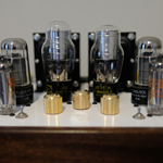
    I've posted about this design before, but am looking for help as I continue to refine the sound and design a crossover topology that best takes advantage of the components in the system that I've built.

    Name:  JBLsystem.jpg
Views: 5713
Size:  54.6 KB

    Design goals:

    • Build a speaker that sounds great with these great components that I can have for years without the urge to upgrade.
    • Build a sensitive speaker that can be powered, in part, to adequate volumes with my 300b amps and sound good in my small listening room.
    • Build a speaker that takes advantage of the MiniDSP for cross-over/EQ duties.


    Background:
    • I had the opportunity to purchase a number of excellent JBL parts for a very reasonable price. These include 2 x 2226J 16 ohm woofers, 2 x 2445J 2" Compression Drivers, 2 x 2405 super tweeters and 2 x 250 Hz tractrix waveguides.
    • I also picked up a miniDSP 4x10 HD for my desire to not spend a fortune on crossover components while I tweak the crossover.
    • Amplifiers include a pair of 300B monoblocks, which power the 2445s, and 2x Crown D45 amps, which power the 2226s and 2405s.
    • I've been living with 2226s built in what I would call "draft" enclosures: ~ 4 cu ft. vented MDF enclosures tuned to 45 Hz with the horns/waveguides and super tweeters mounted on the top on the enclosures. I lift the bass with DSP.
    • They sound pretty good as-is and give me the sense that these components could sound exceptional with the right crossover configuration.


    So that is what the thread is about -- the next steps in putting together this system.

    The drivers:
    • The JBL 2445J is a 2" compression driver with a titanium diaphragm. Part of this build will be to replace the stock diaphragms with the Truextent Beryllium replacement diaphragms. I have these coupled to 250 Hz tractrix waveguides, and mounted on aluminum stands.
    • For woofers, I have the JBL 2226J 15" 16 Ohm drivers. I am pretty happy with their performance in the 4 cu. ft. enclosures, but they could be better -- I think giving them a bigger enclosure, and tuning them deeper could improve their performance. I also have the MiniDSP available to me for tweaking.
    • The super tweeters are 2405s. They are crossed over at 8 kHz and I find them kind of harsh. They may stay in the system or may not depending on the performance of the 2445Js with new diaphragms.


    I am looking for help on how best to measure this system and design the crossover using the MiniDSP.

    Right now I have my crossover is configured as follows.

    Woofers:
    20 Hz LR4
    500 Hz LR4
    35 Hz +8 dB Q 0.8

    Midrange:
    500 Hz LR4
    8000 Hz LR4
    1000 Hz -3 dB Q 1
    400 Hz -4 dB Q 2
    .3 ms delay

    Tweeters:
    8000 Hz LR 4
    1.05 ms delay

    I also have a protection cap network for the MF and HF drivers.
    Name:  crossover.jpg
Views: 4454
Size:  102.5 KB

    So anyways -- looking for some inspiration, ideas, and feedback. If you are interested on where I am taking this, please feel free to follow along. Hopefully I can turn this system into something special.

  2. #2
    Senior Member
    Join Date
    Sep 2013
    Location
    Flat Earth
    Posts
    181
    Your system looks good already. Much better than my random stack

    Have you considered throwing a pair of JBL 2123's in there? They're cheap and great. Maybe have them run from ~300-1.2kHz.

    What kind of hardware and software will you be using to take measurements and will you be measuring inside or outside?

    What diaphragms will you be getting for your 2445's?

  3. #3
    Member danvprod's Avatar
    Join Date
    Dec 2013
    Location
    US
    Posts
    67
    Quote Originally Posted by DingDing View Post
    Your system looks good already. Much better than my random stack

    Have you considered throwing a pair of JBL 2123's in there? They're cheap and great. Maybe have them run from ~300-1.2kHz.

    What kind of hardware and software will you be using to take measurements and will you be measuring inside or outside?

    What diaphragms will you be getting for your 2445's?

    Thanks! I'm sure your random stack is nice too! Interesting thought on the 2123s. Mid-coupler might help the crossover between the 15" and the horn for sure. I could put it in a nice, damped sealed box or tube. I'll investigate.

    I have REW for measurement and nice measurement mic and a Focusrite scarlett 2i2 for measurement. I'll plan on doing some outdoor measurements after it cools down a bit here. I've done some measurements inside.

    These are in-room measurements, with crossovers as described in the first post.
    2226:
    Name:  2226.png
Views: 3532
Size:  39.8 KB
    2445:
    Name:  2445.png
Views: 3408
Size:  45.7 KB
    2405:
    Name:  2405.png
Views: 3357
Size:  37.0 KB
    L/R FR
    Name:  InRoom.png
Views: 3441
Size:  57.9 KB

  4. #4
    Member danvprod's Avatar
    Join Date
    Dec 2013
    Location
    US
    Posts
    67

    Network Schematics

    I did find all of the network schematics here. And also learned something that I want to verify:
    1) There really is only one version of the 2405, and it's not really 8 or 16 ohms, it is more like 10, even though it says 16 ohms.

    Looks like there is 3 crossovers to look at for the 2405:

    3155: http://www.jblproservice.com/pdf/Net...%20Network.pdf
    3145: http://www.jblproservice.com/pdf/Net...%20Network.pdf
    3107: http://www.jblproservice.com/pdf/Net...%20Network.pdf

    The 3107 seems to be the most straight-forward. I don't know what the variable inductors are in the 3155 and 3145. But the 3107 seems to be closest to my previous post. 1.0 uF amp-side, .16 mH inductor and 1.5 uF speaker side with an 8 ohm l-pad.

    3145/55 have bypass caps on the two caps, more resistors parallel to the load and what looks to be an adjustable inductor. Sorry I am a novice at this stuff. I appreciate all the help.

  5. #5
    Senior Member grumpy's Avatar
    Join Date
    Oct 2003
    Location
    SoCal
    Posts
    5,743
    I don't know what the variable inductors are in the 3155 and 3145
    Fixed/tapped, not variable. Acts as an inductor element, impedance matching transformer/level shifter.

    Hard to obtain exact replacements, and as you've noticed, alternatives exist

    Difficult to DIY without a lot of learning about core materials, a winding jig, and some test equipment
    (not on my bucket list).


    ... and yes, just the one 077/2405 at 10-12 ohms where it matters.

  6. #6
    Senior Member berga12's Avatar
    Join Date
    Jan 2016
    Location
    Italy
    Posts
    221
    Ivica, you should measure the Loudspeaker in real condition to check Impedance curve response, then calculate the filter based on Real Impedance at desired frequency, A nominal Freq can't be used, especially if he would like to cut at 500hz, but that's no problem because he will use the DSP for HP.

    In general the value you suggest for the 24db are quite fitting with reality because you are cutting Far Far away to Resonance freq and horn resonance so impedance value are closer to nominal.

    A check with Loudspeaker with an instrument like CLIO board or DATS or and Impedance measurment during frequency operation should be a must, especially on old loudspeakers.

  7. #7
    Senior Member ivica's Avatar
    Join Date
    Jan 2008
    Location
    serbia
    Posts
    1,703
    Quote Originally Posted by berga12 View Post
    Ivica, you should measure the Loudspeaker in real condition to check Impedance curve response, then calculate the filter based on Real Impedance at desired frequency, A nominal Freq can't be used, especially if he would like to cut at 500hz, but that's no problem because he will use the DSP for HP.

    In general the value you suggest for the 24db are quite fitting with reality because you are cutting Far Far away to Resonance freq and horn resonance so impedance value are closer to nominal.

    A check with Loudspeaker with an instrument like CLIO board or DATS or and Impedance measurment during frequency operation should be a must, especially on old loudspeakers.
    Hi berga12,

    I can understand all the mentioned, but if someone want to put 2405 with 244x to improve UHF and dispersion response what would You suggest him, if only passive filters 'are on the table'?

    I do not understand what is so special with "...especially on old loudspeakers...", is it their age or technical operating condition, I think technical operating condition of newer drivers can involve some troubles if were treated unappropriated.

    If we are talking about DSP driven FIR filters speaker active networks, then appropriated spacial measurements have to be done in order to compensate most of the drivers , or even ambience, "irregularities" , but to do that a person has to be properly educated with the experience in that fields.

    Try to do high resolution measurements of the F/R of the speakers that are on Your avatar, and try to move the measurements mic 50cm left or right and make another measurements and compare them, then up and down, and compare all, after that if You decide to "throw them away" please INFORM us before, where would be that place, so we can ...... :-))

    regards
    ivica

  8. #8
    Member danvprod's Avatar
    Join Date
    Dec 2013
    Location
    US
    Posts
    67

    More details about the protection crossover

    Here is an annotated picture of my protection crossover. The 2445 is 1.5 octaves below my crossover frequency. The 2405 is 2 octaves below. Both caps are bypassed and there is a 47 Ohm resistor placed parallel to the input, an idea I got from several other threads here.
    Name:  Crossover.jpg
Views: 4118
Size:  107.8 KB

  9. #9
    Senior Member berga12's Avatar
    Join Date
    Jan 2016
    Location
    Italy
    Posts
    221
    Quote Originally Posted by danvprod View Post
    Here is an annotated picture of my protection crossover. The 2445 is 1.5 octaves below my crossover frequency. The 2405 is 2 octaves below. Both caps are bypassed and there is a 47 Ohm resistor placed parallel to the input, an idea I got from several other threads here.
    Name:  Crossover.jpg
Views: 4118
Size:  107.8 KB


    In case your DSP fail with filter, and you are running good amount of power you will DESTROY your diaphagram with those value.

    2405 is not happy below 6,5khz 18db (not 6!!!!)
    2445 is really not happy below 200hz!!!!!

    pay attention, diaphagram for 2405 are nearly not existing anymore....

  10. #10
    Senior Member berga12's Avatar
    Join Date
    Jan 2016
    Location
    Italy
    Posts
    221
    Dear Danv, pay a lot of Attention on "copying networks around".


    for the 2405, do Streight forward, every schemathics is similar on every crossover, some use tapped autotransformer, some LPAD (see 3155 equivalent), but more ore less are similar, I use 1,5uF - 0,14mH - 1,8uF and my L pad is 4.3ohm series and 36ohm parallel.

    for the 2445 you can concentrate on Low Pass, as I told you value like 0,48mH and 1uF could fit for a cut on top about 8-10Khz

    for the High pass If you want to Run PASSIVE high pass, remember that every studio monitor cut the driver at 1,2-1,5Khz, and you need something around 400hz (theoretically 2xHorn Fc, means 250hzx2= 500hz....)

    and for 400-500hz the value Are much bigger than the 4343 or 4355 filter... (notice that only 4350-55 have 2" Driver!!!! like 2445)

    Yes you need an LPAD setup on 16ohm for 2445, Just search LPAD calculation and place 16ohm and the required Db attenuation -3 -6 -9 -12 etc... between 2405 and 2445 should be around 6/9db of difference.

    This is always Just my opinion! Not a Must.

  11. #11
    Senior Member
    Join Date
    Apr 2016
    Location
    san diego
    Posts
    315
    you can start from getting rid of that white horn, and selling it to me
    Semper Fidelis

  12. #12
    Senior Member
    Join Date
    Sep 2013
    Location
    Flat Earth
    Posts
    181
    About the 2123, yes, you should def. investigate. It's very efficient and can handle 250W too. The box can be very small. My system is fully active (and I know next to nothing about passive crossover theory). The 2123 is between 2226 & 2446. BW 24dB/oct filters + correction filters and time alignment.

    I actually made a thread asking about advice on protection networks yesterday, so the annotated picture of your network was a positive surprise. What is the point of the 47R resistor and the 0.01mF cap, and what voltage rating does that chunky 50mF resistor have, please?

  13. #13
    Member danvprod's Avatar
    Join Date
    Dec 2013
    Location
    US
    Posts
    67
    Quote Originally Posted by DingDing View Post
    About the 2123, yes, you should def. investigate. It's very efficient and can handle 250W too. The box can be very small. My system is fully active (and I know next to nothing about passive crossover theory). The 2123 is between 2226 & 2446. BW 24dB/oct filters + correction filters and time alignment.

    I actually made a thread asking about advice on protection networks yesterday, so the annotated picture of your network was a positive surprise. What is the point of the 47R resistor and the 0.01mF cap, and what voltage rating does that chunky 50mF resistor have, please?
    Do you have a thread about your build? I'd be interested in seeing what you have developed. I'm glad the protections network diagram helps.

    Here was the thread I found the crossover idea on: http://www.audioheritage.org/vbullet...p/t-19613.html

    My 50 uF is 250v btw. The 47 Ohm resistor is to cut the impedance peak at 750 Hz; it's suppose to be a damping resistor. The 0.01 uF cap is a bypass cap.

    Here is the info about the bypass caps: http://www.hawthorneaudio.us/forums/...php?f=1&t=3763

  14. #14
    Senior Member
    Join Date
    Sep 2013
    Location
    Flat Earth
    Posts
    181
    Quote Originally Posted by danvprod View Post
    Do you have a thread about your build? I'd be interested in seeing what you have developed. I'm glad the protections network diagram helps.

    Here was the thread I found the crossover idea on: http://www.audioheritage.org/vbullet...p/t-19613.html

    My 50 uF is 250v btw. The 47 Ohm resistor is to cut the impedance peak at 750 Hz; it's suppose to be a damping resistor. The 0.01 uF cap is a bypass cap.

    Here is the info about the bypass caps: http://www.hawthorneaudio.us/forums/...php?f=1&t=3763
    Thank you!

    Unfortunately, there's no thread for them as of yet, but I did some research on here a while back which may be of interest to you as it is fairly close to what you're doing. Please look at the DingDing goes DIY thread here.

    It's still a work in progress, but the system is basically 2404, 2446 in 2360A, 2123 and 2226 + subs for the lows. I tried without the 2123, but I could never really get the magic happening from 250-300ish up to around 1kHz until the 2123 was added. That is not to say it's not possible! It just means I couldn't do it, and my experience is not that vast. I've been so happy with the performance that development went sluggish for a while and I've just recently started picking up on it again.

  15. #15
    Senior Member berga12's Avatar
    Join Date
    Jan 2016
    Location
    Italy
    Posts
    221
    Just in my mind, if I remember well, 2445+Horn(kh55) is about 110-111db/W/m, the 2405 is about 105-106db/W/m realistic...

    so depending on your ear sensitivity you have around 6db between 2445 and 2405. With a biamp in your case it could be that you don't need attenuation on the 2405 and you can go down with full mid high using your DSP and adjust level between the mid and super tw. Actually most of audiophile, or like Klipsh filter uses variable Autotrasformer only on Mid Driver.


    You need an HIGH PASS done via your DSP and a protection cap, Around 400-500hz (theoretically 500hz, 2 times horn Fc)

    ___________________________________

    JBL studio monitors (like 4350-55) uses the 2" driver from 1,2Khz to 10Khz, but this is not your case, so forget about this sentence and don't look at HP session in JBL studio monitors filter schematics.

    ___________________________________

    I'm shure you will be happy with That, if possible in the meantime, use Crown D45 bridged on 2226J

Thread Information

Users Browsing this Thread

There are currently 1 users browsing this thread. (0 members and 1 guests)

Similar Threads

  1. DIY 2225J, 2445J, 2405 Build Help
    By danvprod in forum Lansing Product DIY Forum
    Replies: 22
    Last Post: 06-08-2014, 11:30 AM
  2. 4722-HF (2432H) to 2226H crossover point/slope (active crossover)
    By Jonas_h in forum Lansing Product DIY Forum
    Replies: 6
    Last Post: 04-25-2012, 12:17 AM
  3. JBL 2225J& 2445J Crossover
    By sky-audio in forum Lansing Product Technical Help
    Replies: 4
    Last Post: 08-12-2009, 03:52 PM

Posting Permissions

  • You may not post new threads
  • You may not post replies
  • You may not post attachments
  • You may not edit your posts
  •