Yes, a schematic would help
and the caps don't have to be the same value,
although same type and order of magnitude in value
is probably a good idea.


Yes, a schematic would help
and the caps don't have to be the same value,
although same type and order of magnitude in value
is probably a good idea.

I thought there was a schematic for the CC Crossover somewhere here in the vault but I was unable to locate it.
Just Play Music.
I'd like to know how those terminal strips are connected on the bottom side - seems like a lot of components connected to nothing, but the quad wire (L-Pad?) is hooked up the same way, so there has to be something going on.
There are a few different 4345 CC schematics floating around, but posting the wrong one would probably just add to the confusion.
The one in post #5 http://www.audioheritage.org/vbullet...l=1#post175125
appears to have some of the same capacitor pairings - I see a 24/24 a 15/9.1 but no 24/12
Thanks for the schematic Jeff, I looked at it and the other one referenced in that post by Heather. Way over my head and I don't have the time to learn electronics right now .Originally Posted by JeffW


Just Play Music.
I was able to replace the resistor this morning, make the connections, fired 'em up and its back in action.
I don't like to mess with all that electrical stuff & thin little wires so I think I will leave well enough alone.
Thanks everyone for all your help, hopefully I wont have to re-visit this thread any time soon.
Now to address that pesky ground loop.

Just Play Music.
Beautiful layout
Expensive
High parts count
And all tied together with crappy crimp connections
THAT is you problem(s)
Have someone properly solder all those lugs and spades in the networks and you won't have anymore of these phantom/intermittent issues, I promise
And if you ever need a resister like that again, please PM me. If I am here and I have it in house I will happily drop one in the mail to you. Don't pay shipping for a .10 cent part
I have plenty of 1%ers better than that metal film shown in your photo
You should also consider investing in an inexpensive DVOM so that the next time you THINK you have a bad resister you can check it yourself in about 2 seconds and eliminate a great deal of wasted time and useless speculation
It could also (if you are willing, or want to try) help you find your intermittent connection
You can pick one up good enough for this task for about $5 bucks (I have these all over the house, like pencils and paper):
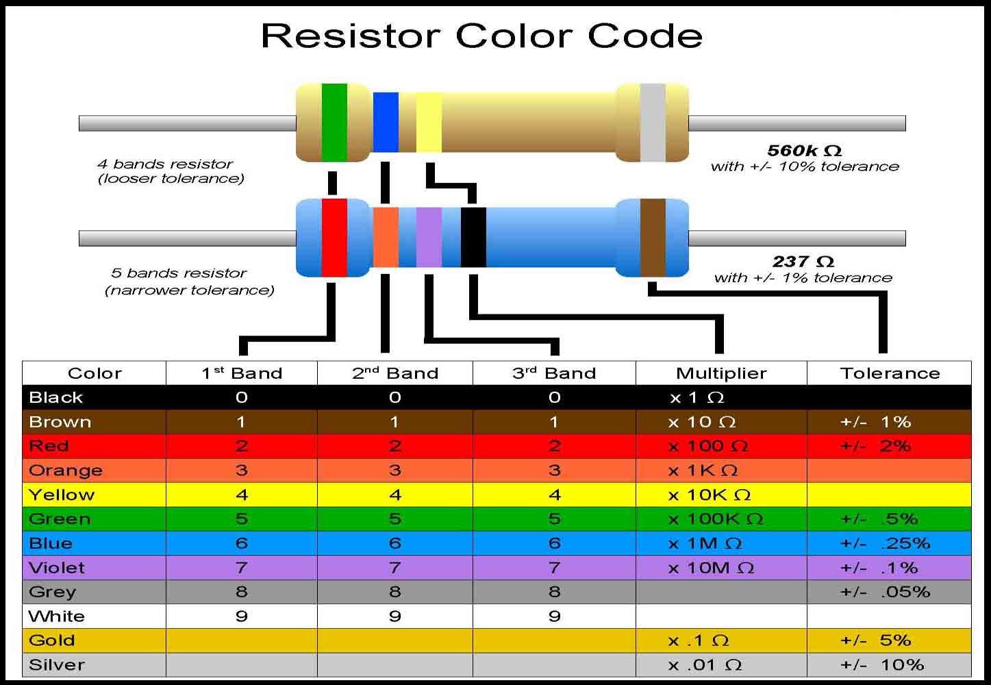
Won't hurt to familiarize yourself with this as well (print one out and tape it to the fridge; if you don't like this one there's about a million versions on-line):
Hey Wagner. Yeah, I was thinking the same thing this morning, aint too crazy about the crimps myself. When I installed the new res to the spade I crimped & soldered it, that just seems to make a lot more sense . If I have these issues again I will remove x-over from speaker, find prob & while its out solder all the spades.
Thanks for the diagram I did "consult" it when I was trying to find/identify the one I had. I ordered a bunch of resistors, I think about a dozen so I should be good for a while on that end, thanks for your offer nonetheless.
When its running smoothly it is a great system but the fact that its bi-amp only has its own drawbacks, sometimes I wish it was just passive and not have to deal with the extra amp & external crossover. I just put in some new gear in place hence the issues. There's something to be said for simplicity, which is something I am striving for all around
This weekend the groundloop, fun fun fun!
Just Play Music.
Well, you can start by finishing up the assembly job on those networks with a hot iron, some good flux and a little solder
What is the "ground loop" problem? How do you know that is what it is?
Most can be resolved with common sense
Have fun,
Thomas
I thought I had common sense but I wonder sometimes. I don't know if its a proper ground loop, but when there is nothing playing/no signal the speakers emit a "Hum".
What I have rigged up here is actually quite the opposite of simplicity.
Then new amps and Pre amp are mark levinson which use a camac/fisher interconnect, cool little pieces but doesn't mix well with other conventional gear ie: RCA Xlr.
I had to make all the interconnects to hook up various pieces of gear which all (aside from the MK) are XLR, so the interconnects are camac on one end and xlr on the other.
Lots of wires & Tv equipment all next to each other which just aggravates the whole process.
Bottom line is I have to mess with it this weekend & see if I cant figure out what is causing the Hum.
Here's a picture of the Camac ic. this is cam to rca.
Just Play Music.
Cool, learn something new every day.
Al
You're right Grumpy, I did find some "oddities" when I pulled out the Cross over. I will elaborate and post some pictures to illustrate. A bit of a mystery still but it could also be my clumsiness.
More to come.
Just Play Music.
Where's Wagner/Thomas? has he been sent on a temporary hiatus?
Just Play Music.
There are currently 1 users browsing this thread. (0 members and 1 guests)
 Posting Permissions

 Reply With Quote
