Page 12 of 58 FirstFirst ... 2101112131422 ... LastLast
Results 166 to 180 of 864

Thread: Project M2 DIY Thread

  1. #166
    Obsolete
    Join Date
    Apr 2003
    Location
    NLA
    Posts
    12,193
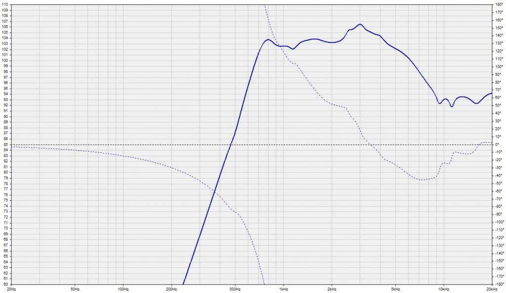
    I did a quick shot of the 476Mg versus the D2430K on the M2 waveguide. I needed the impedance curves so I figured I'd collect some SPL curves at the same time.
    Attached Images Attached Images  

  2. #167
    Member sebackman's Avatar
    Join Date
    Feb 2004
    Location
    Europe
    Posts
    675
    Hi 4313b,

    From the text below the graph it looks like a very long time window Is that correct?

    It also seems like Mg is falling off reasonably early and showing a similar pattern as the Be. That should be just fine with a DSP but given the difference betwee the drivers the correction file will need to be rather different.

    Excellent info, thank you

    Kind reargs
    //RoB
    The solution to the problem changes the problem.
    -And always remember that all of your equipment was made by the lowest bidder

  3. #168
    Senior Member
    Join Date
    Nov 2008
    Location
    Gothenburg, Sweden
    Posts
    761
    Quote Originally Posted by 4313B View Post
    I did a quick shot of the 476Mg versus the D2430K on the M2 waveguide. I needed the impedance curves so I figured I'd collect some SPL curves at the same time.
    The off-axis curves would be very interesting to see, if you measured that?

  4. #169
    Obsolete
    Join Date
    Apr 2003
    Location
    NLA
    Posts
    12,193
    Quote Originally Posted by sebackman View Post
    Hi 4313b,

    From the text below the graph it looks like a very long time window Is that correct?
    Right, I didn't gate the posted curves above nor did I measure them outside (raining) like I usually do. I didn't like how the gating affected the response around 500 to 1kHz. Usually I use tail correction in LEAP instead. For example, in this instance I would use tail correction below approximately 300 to 400 Hz.

    I'll do the SPL curves that I will end up using outside some night soon. It appears that the 476Mg won't require nearly as much compensation on the top end, just like GT theorized.

    Quote Originally Posted by sebackman View Post
    That should be just fine with a DSP but given the difference between the drivers the correction file will need to be rather different.
    Yep and that is the main thing one can take away from this quick set of graphs, the compensation filter for both drivers would be quite different.

    Quote Originally Posted by bubbleboy76 View Post
    The off-axis curves would be very interesting to see, if you measured that?
    Yeah, I suppose I could mark off a spot at 30 degrees off axis.

  5. #170
    Senior Member grumpy's Avatar
    Join Date
    Oct 2003
    Location
    SoCal
    Posts
    5,743
    Sorry to be a dolt... (&thanks for the plots):
    Mg is green?
    Less compensation meaning less complicated vs D2?
    (or have I got this upside down).

  6. #171
    Senior Member pos's Avatar
    Join Date
    May 2007
    Location
    France
    Posts
    2,629
    D2430k must be the green curve.

    For comparison here is, with the same scale, the inverse of the EQ applied by the crown and passive network to make the D2430k flat (on average in the listening window).
    This should be a fair representation of the natural response of the D2430K on the M2 waveguide.
    Name:  D2M2.jpg
Views: 2449
Size:  87.3 KB

  7. #172
    Senior Member pos's Avatar
    Join Date
    May 2007
    Location
    France
    Posts
    2,629
    Quote Originally Posted by johanwholst View Post
    Did note have time before today to rough-tune 2450sl/be in the M2 waveguide. Well, it took about 10 seconds to conclude that 2450sl with truextent to my ears completely parks D2

    Attachment 71409
    Nice!
    I am eager to try mine, but given the difficulty in swapping these, this is not going to happen right now.
    I like the way you cut the walls of the waveguide mounting part to make the nuts easier to reach.

  8. #173
    Senior Member
    Join Date
    Oct 2014
    Location
    Iceland
    Posts
    140
    Quote Originally Posted by pos View Post
    Nice!
    I am eager to try mine, but given the difficulty in swapping these, this is not going to happen right now.
    I like the way you cut the walls of the waveguide mounting part to make the nuts easier to reach.
    You got a keen eye Thomas! It was actually done by forum member hlaari. Without it mounting would be utter pain. Now it is just fiddly

    One question: I'm about to mount the WG to the baffle.

    Two options: Tap the plastic with m5 and use bolts, or glue threaded rod in the hole?

    I believe the plastic for flange mounting strong enough for supporting 2450sl so I will not brace the compression driver. Crazy?

    Another thing: My wife waits eagerly to see me mounting the waveguide from the back. She this it's going to be quite entertaining with me halfway through the baffle hole and a lot of x rated language.
    Kind of regret I did not build an access hatch on the back...

  9. #174
    Senior Member pos's Avatar
    Join Date
    May 2007
    Location
    France
    Posts
    2,629
    Quote Originally Posted by johanwholst View Post
    Without it mounting would be utter pain. Now it is just fiddly
    It is painful indeed, especially when the nut gets magnetized...

    The easiest way I found is to maintain a distance between the driver and the waveguide so that the threaded rod only exceed a tiny bit over the adapter.
    That way you only have to get the nut above the hole and gently turn it while it stays nicely flat...
    Still cumbersome, to say the least.

    Two options: Tap the plastic with m5 and use bolts, or glue threaded rod in the hole?
    I did a mix of the above: I used M6 threaded rods for mounting the waveguide to some metal brackets (no real baffle for now) with wing nuts.
    I drilled the hols with a 5mm drill, but it is probably not necessary (Rob did not for example) as the holes are already 4.7mm.
    Wing nuts are a good option if access is difficult.

  10. #175
    Obsolete
    Join Date
    Apr 2003
    Location
    NLA
    Posts
    12,193
    Quote Originally Posted by pos View Post
    D2430k must be the green curve.
    Yes. I am not liking the looks of the 476Mg. I played around with the data - gating, smoothing, etc and the D2430K looks fine, 476Mg not so much.

    I'll measure the other 476Mg at the same time I redo the measurements outside and determine if they need to be opened up for inspection.

    Quote Originally Posted by grumpy View Post
    Sorry to be a dolt... (&thanks for the plots):
    Mg is green?
    Less compensation meaning less complicated vs D2?
    (or have I got this upside down).
    I forgot to post which was which. D2430K is green. I wasn't all that excited about the results anyway. I primarily just needed the impedance curves for the time being and shot the SPL curves just because (in the living room on the floor, waveguides face up towards the ceiling).

  11. #176
    Senior Member srm51555's Avatar
    Join Date
    May 2013
    Location
    Wisconsin
    Posts
    623
    Quote Originally Posted by johanwholst View Post
    Kind of regret I did not build an access hatch on the back...
    I was thinking the same thing before I mounted mine. For me, I am glad I did it this way, mounting them wasn't really that bad. Finding the correct hole spacing was much worse I thought .

    Maybe she should screw them in since her hands are smaller.

  12. #177
    Senior Member
    Join Date
    Oct 2014
    Location
    Iceland
    Posts
    140
    Yes, the hole spacing proved difficult to measure properly is quite a bit off on mines so they are overzized... Blutack will seal it all up in the end

    By the way, tapping for M5 direct went smoothly. Just finished it
    Thanks for the tip on wing nuts Pos. that's what I will do

  13. #178
    Senior Member pos's Avatar
    Join Date
    May 2007
    Location
    France
    Posts
    2,629
    Yes M5 is easy to drill as you are supposed to drill a 4.2mm hole and the existing holes are 4.7mm IIRC.
    That means that the grip will not be as good as the fillet will not be as deep as it is supposed to.
    As long as you don't pull perpendicularly to the waveguide plan everything should be fine :P

    I went for M6 for the mounting holes, which calls for a 5mm pre drilling, and used M5 for mounting the drivers because I wanted to keep as much material as possible there.

  14. #179
    Administrator Robh3606's Avatar
    Join Date
    Apr 2003
    Location
    Rocinante
    Posts
    8,204
    Hello 4313b

    Here is a passive compensation voltage drive for M2 waveguide with 476mg It looked pretty good with my pair. You have a issue with the drivers?? Simulated on axis with network and schematic.

    Rob
    Attached Images Attached Images     
    "I could be arguing in my spare time"

  15. #180
    Obsolete
    Join Date
    Apr 2003
    Location
    NLA
    Posts
    12,193
    Nice Rob!

    Quote Originally Posted by Robh3606 View Post
    You have a issue with the drivers??
    Yeah, I might have an issue with the 476Mg I measured. Hopefully I'll be able to check it in the next few days.

    Did you use ideal inductors in your model or did you apply some DCR?

Thread Information

Users Browsing this Thread

There are currently 1 users browsing this thread. (0 members and 1 guests)

Similar Threads

  1. JBL LN3 Project, *Official Thread
    By Nightbrace in forum Lansing Product DIY Forum
    Replies: 58
    Last Post: 07-13-2016, 03:08 PM
  2. Fundraising request; donations to Lansing Heritage Project May loudspeaker project
    By mikebake in forum Lansing Product General Information
    Replies: 7
    Last Post: 04-21-2011, 12:37 PM
  3. Project May, similar privat project?
    By Flodstroem in forum Lansing Product DIY Forum
    Replies: 14
    Last Post: 02-21-2007, 03:42 PM

Posting Permissions

  • You may not post new threads
  • You may not post replies
  • You may not post attachments
  • You may not edit your posts
  •