Hey folks,
I´d like to swap the original L-pads in the 4355 to some fixed resistors.
Which values would I need to reach the +4db setting of the L-pad for the HF and UHF section
Thanks a lot,
Olaf


Hey folks,
I´d like to swap the original L-pads in the 4355 to some fixed resistors.
Which values would I need to reach the +4db setting of the L-pad for the HF and UHF section
Thanks a lot,
Olaf
Take the value at +4 on your L-Pad and you'll have it. But I believe that if you have it at +4 it's like you don't have any. (L-Pad)...Originally Posted by Dr.db

I would disconnect it...
cheers!
Thanks for your help
Actually I haven`t got the oppertunity to measure the values, sorry. But you think I could simply bypass the L-Pads!?

3155 has two L-pads. One 16 ohm and one 8 ohm.
Remove L-pad will affect the crossover frequency.
Set L-pad to +4, disconnect cables and measure the value between the legs.
43XX (2235-2123-2450-2405-CC 3155)5235-4412-4406-4401-L250-18Ti-L40-S109 Aquarius lV-C38 (030) 305P MkII
"Here is what I get measuring an L-Pad." (Quote:4313B)
http://www.audioheritage.org/vbullet...eling-networks
This is what I found for the 8ohm L-Pad. But I´m not shure how to read this....
The "series resistor" (3 to 2) varies from 7.2ohms to 0 ohms, so I guess I could simply cancel this resistor!?
But which value does the remaining "parallel resistor" has to be ?
If you can find my 3155 charge coupled schematic it should have the fixed resistor values in it.
Thanks for the hint
So it would be none series-resistor and a 100giga-ohm in parallel ?
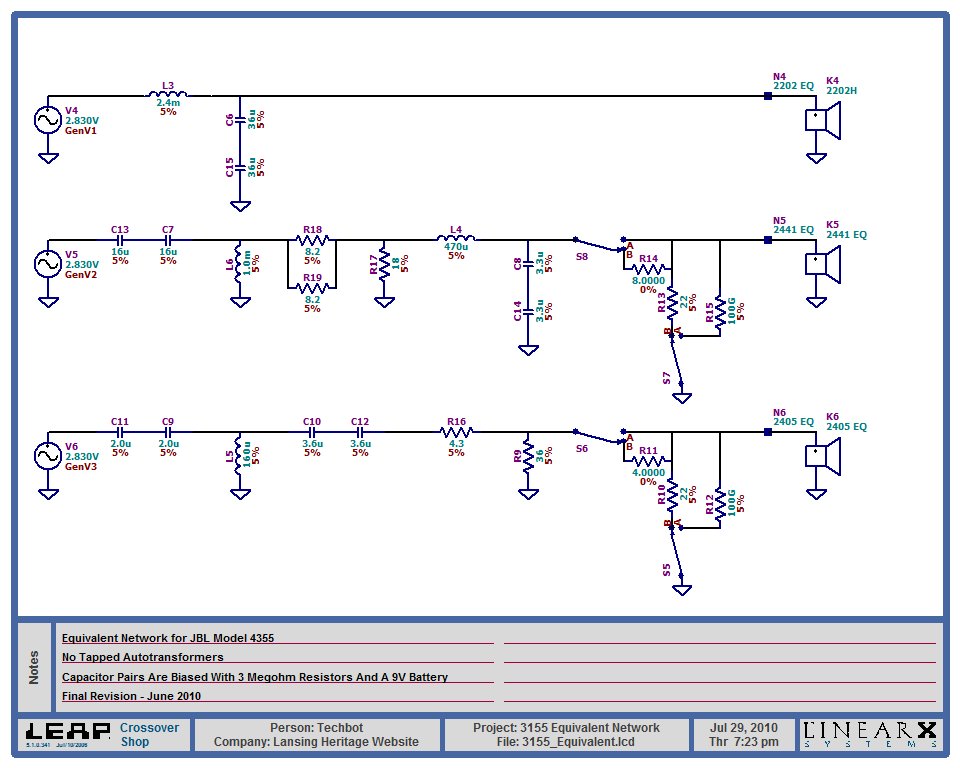
No, the 16 ohm L-Pad measured 8 ohms in series and 22 ohms in parallel at the 0 position and the 8 ohm L-Pad measured 4 ohms in series and 22 ohms in parallel at the 0 position.

I'd say to make sure the 100Gig ohm resistor is non-inductive
and that 1% might sound better, but someone might take me seriously.
(a -really- poor idea)
Sometimes including non-physical parts (particularly DC resistive paths to ground)
help electrical simulations run properly.
That is for the "B-position" and is the 0 position setting as you mentioned.
But I´m looking for the +4db setting.
I thought this would be the "A-position" without a series resistor and just the 100gig ohm parallel resistor?

So, If I decided to run at 0db without variable Lpad I've absolutely to place in the crossover an 8/22ohm for the 2441 and a 4/22ohm for the 2405, otherwise it changes crossover point?
I would agree, but I´m not really a technician to ultimatly varify it
Ok I purchase themlets try!
There are currently 1 users browsing this thread. (0 members and 1 guests)
 Posting Permissions


 Reply With Quote