Nice job Don and my own project will be very similar......
yea, looks to be very helpful those clamps. Should maybe invest in a couple of pairs.........Originally Posted by JeffW


Nice job Don and my own project will be very similar......
yea, looks to be very helpful those clamps. Should maybe invest in a couple of pairs.........
Flodstroem

Those are bar clamps from Harbor Freight tools. I like the rectangular channel design. It allows them to remain standing upright while assembling the speaker on top of them. By the way, that was just the first mock up. I decided to move the clamps right out to the corners of the boxes before clamping with glue.
http://www.harborfreight.com/60-in-a...amp-60673.html

Coming along very nicely Don!!
Thanks for documenting the whole process!
How tough is it to get the bolts or nuts (which ever you chose) under the M2 mounting ring for the 2452?
Thanks again!
Always fun learning more.......
Installing the larger compression driver is not easy. JBL intended for the horn to be used with the smaller size D2 and that allows them to assemble the plate to the driver first, then the plate to the horn. We can't do that with the larger drivers.
You will want to choose 1/4-20 X 1 inch long set screws to go into the compression driver, and regular 1/4 inch nuts to fasten to the plate. The space between the plate and the horn is tight, but the parts can be assembled with some patience. I had to use my pinky fingers to start the nuts. I worked with the driver on the bottom and the horn on top, sitting at the edge of a table. I used the tip of a flat a screwdriver to hold the two parts slightly separated to get all 4 nuts started. After struggling with the method for 15 or 20 minutes on the first horn, the second one went right together in only a couple of minutes of work. The #10-14 x 1.5 inch plastite screws worked perfectly on the horn to plate assembly.
Yes that is kind of what I gathered from the looks of things. I am thinking the 2451 will be a tiny bit easier than the smaller bolt pattern but not much. Just a wee bit more room for the fingers.
Always fun learning more.......
I'll catch the group up on my progress. I have plenty of photos.
Here I'm gluing a sheet of MDF to the baffle to make it thicker. Due to memory failure I selected the wrong thickness, it's only 1/4 inch, and it should have been thicker. I'll just leave it as is. It stops well short of the edge of the baffle to leave room for the grille cloth frame and a decorative molding. In various photos you can see that I'm adding wood filler wherever the surfaces aren't quite flush, I tend to build it up too high on purpose, and it will be sanded down flush later. This is all going to be hidden later anyway.
Here I have drilled the holes and made the cutout for the horn and I'm test fitting it. You can see some plastic templates that I made for this task in the last picture, but they didn't transfer the pattern well. I would have been better off to just lay the pattern out in pencil and drill. That's what I did on the other speaker and it came out better. But it's not really a problem, I just ovalled the holes a bit as needed to make it fit.
Here I'm looking at the woofer and port layout, with a template.
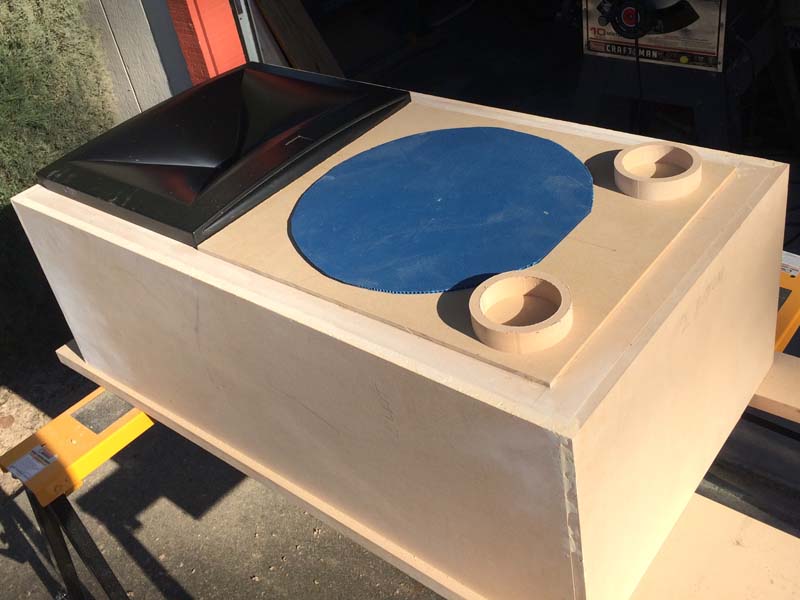
Next was the holes for the woofer. This was my first time trying out this Jasper circle jig. Drill a 1/8 inch hole in the center. Set the circle jig to 15.25, plunge to 5/16, and start cutting. Reduce the circle size by a half inch and repeat. After getting down to 13.75, plunge all the way down to 1 inch and cut again. Then set the plunge deep enough to cut all the way through, and cut all but an inch in two opposite locations. I didn't want to finish the hole with the router because the jig is fixed to the center, and you don't want the router going off center or falling through when it cuts the last bit. I finished the holes with the sabre saw. I found this to be a fun part of the build, and not too difficult.
I also used the jig to make some collars. I started with the inner diameter set to the same as the outside dimensions of the cardboard port tube. Then increase the size by 1 1/2 inches and cut again to make the collar. You have to make sure that you have scrap wood underneath, and make sure that the center pin goes all the way through into the scrap. Even doing that, some of the collars came out eccentric, they wouldn't do if the outer circle was important, but for this, its not. These will be glued to the back of the baffle. They should make it easy to experiment with different port lengths. Just a small dab of RTV will hold the tube into the collar, and if I want to cut the tube it should twist free easily. And with the port tube installed flush to the back of the baffle instead of to the front of the baffle, I can use the roundoff bit on the router to flare the port hole in the front.

I made some more collars a little bit fancier. I set the diameter to the same as the outside of the port tube, then set the plunge to cut to half the board thickness. Cut the circle. Then set the diameter to the same as the inside of the port tube, plunge to full thickness and cut again. A stepped circle. Then cut the outside circle the same as the other collars. I smoothed the inside with a flush trimming roundoff bit, and voila. Port tube flares, home made.

Cutting out some rectangles for the inside cabinet braces. I wanted the inside holes to have rounded corners so I used a hole saw to make them, and finished the cutouts with the sabre saw.
Putting in the hurricane nuts for the woofer mounting. I used a C-clamp to press them in from behind.

Gluing the inner braces in place.

Starting out on building the back of the cabinet. It has to have a removable panel so that I can install and remove the horn easily. I started with a little strip at the top. Then added a cleat that goes underneath to support the removable section.
Then another cleat. It fits against the cabinet brace. The lower section of the back will be glued so that half of this cleat is showing.
Here I'm gluing those collars in place on the back of the baffle. I used a short section of port tube to center the collar, clamped with glue, then removed the port before it got stuck.

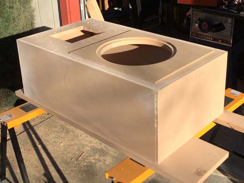
Another mock up, this time with the woofer added.
Last photo for now. It's not finished until it looks as good as this.


Great work Don
Love the mdf flares. I had to cut stepped ports in my B460 clone so the plastic didn't show through on the edge of the cabinet, but I didn't do the extras step of rounding - very cool

Nice work my friend. Good job on the pictures, they are a pain in the rear during the build but appreciated by many after the build.
The hurricane nuts are horrendous if they work loose- I suggest (since they're already installed) putting a small screw (with glue on the threads to really lock it down) with the head securing the flat section of the hurricane nut- that will prevent it from working loose of the MDF when you're removing driver mounting screws. The issue with both those and T-nuts is that you're usually pushing the driver into the screw head when removing to ensure the driver doesn't slip or lose contact with the phillips/hex/whatever. That pressure along with the wiggling from the screw rotation is sometimes enough to push hurricane or t-nuts out from the MDF, and then you're in a tough spot for getting the screw free of the cab.

Very nice work and great documentation!!!
There are currently 1 users browsing this thread. (0 members and 1 guests)
 Posting Permissions


 Reply With Quote