Page 1 of 2 12 LastLast
Results 1 to 15 of 22

Thread: JBL 5235 transformer upgrade

  1. #1
    Member JBLPRO's Avatar
    Join Date
    Mar 2015
    Location
    Kennett Square, PA
    Posts
    55

    JBL 5235 transformer upgrade

    I am in the process of upgraded the transformer in my JBL 5235 to a Talema #70055K tordial transformer as Kenrick sound has done.
    http://media.digikey.com/pdf/Data%20...merCatalog.pdf

    Can someone please shed some light on how it should be connected to the 5235 circuit board. It has 2x 22V secondaries. I am in US so I will only be using one of the 115V primaries.
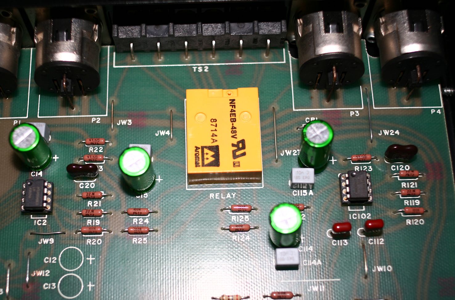
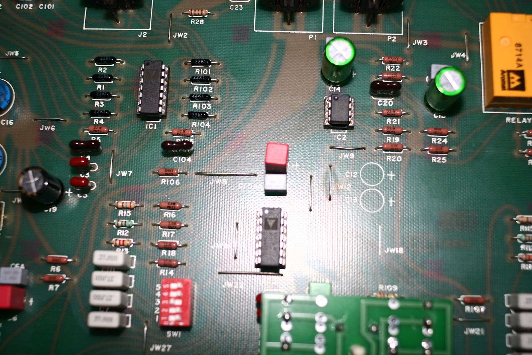
    The wiring I have now is pin 5 and 6 for 115 primary and pin 12 on secondary jumped to pin 13 to ground on 5235 circuit and pin 11 and 14 for AC on 5235 circuit board. I am not sure if this is correct.
    Thanks in Advance. Any help is greatly appreciated.
    mk

  2. #2
    Member JBLPRO's Avatar
    Join Date
    Mar 2015
    Location
    Kennett Square, PA
    Posts
    55
    I did some further checking and I have 17.5 V+ from pin 2 of Q1 which is correct. I have 17.5V - from Q2 pin 2 which is also correct. The issue is that I have noise at the outputs and when I touch C24 220uf cap it cleans up completely. Any clue as to how I may fix out my issue. Unit will pass clean audio when I "ground" that 220uf cap. Level seems very low to me. Ideas?

    mk

  3. #3
    Senior Member martin2395's Avatar
    Join Date
    Apr 2012
    Location
    Europe
    Posts
    928
    No bad solder joints around? I had noise issues with various old stuff and sometimes it was caused by tired/cold joints. The second reason ware just worn out caps, sometimes they had as few as 20-30% of their original capacity left.

    Is the cap itself still OK? We're talking about 30yo+ caps.

  4. #4
    Member JBLPRO's Avatar
    Join Date
    Mar 2015
    Location
    Kennett Square, PA
    Posts
    55
    Quote Originally Posted by martin2395 View Post
    No bad solder joints around? I had noise issues with various old stuff and sometimes it was caused by tired/cold joints. The second reason ware just worn out caps, sometimes they had as few as 20-30% of their original capacity left.

    Is the cap itself still OK? We're talking about 30yo+ caps.
    I replaced all the caps. The one i mentioned i PS with panasonic ECU type 105c I will continue to look for cold solder joints which I also have had issues in other pieces of gear.
    mk

  5. #5
    Senior Member
    Join Date
    Nov 2003
    Location
    Toronto
    Posts
    1,162
    One thing that jumped out of your first post to me is that you say you're only using one of the primaries. Normally, if there are two primaries, they would be connected in parallel for 115/120 VAC and in series for 230/240 VAC. When you parallel them, make sure to observe polarity otherwise there will be cancellation and you'll get nothing across the secondary.

  6. #6
    Member JBLPRO's Avatar
    Join Date
    Mar 2015
    Location
    Kennett Square, PA
    Posts
    55
    Name:  talema 70055K.jpg
Views: 1401
Size:  158.8 KB

    I have included a pic of the talema 70055k transformer. As I stated I am using one of the 115V primaries.

  7. #7
    Senior Member grumpy's Avatar
    Join Date
    Oct 2003
    Location
    SoCal
    Posts
    5,743
    Looks like if you short C24 to ground, you'll likely open the output relays,
    which would quiet things indeed (the LED should be turning on/off as well).

    Are you getting noise on the output with the level controls turned down?
    Any input connected?

  8. #8
    Senior Member
    Join Date
    Nov 2003
    Location
    Toronto
    Posts
    1,162
    Quote Originally Posted by JBLPRO View Post
    Name:  talema 70055K.jpg
Views: 1401
Size:  158.8 KB

    I have included a pic of the talema 70055k transformer. As I stated I am using one of the 115V primaries.
    Yes, but use both and parallel them.

  9. #9
    Member JBLPRO's Avatar
    Join Date
    Mar 2015
    Location
    Kennett Square, PA
    Posts
    55
    sorry for the confusion on grounding C24 220uf/100V cap. I am just touching it with my finger on top and all goes quiet. Leads are soldered correctly. polarity is correct. I am not pressing nearly just making contact with the can. Reduction of noise greatly reduced when touching side but noise totally eliminated when touching metal top of cap.

    TROUBLESHOOTING RESULTS:

    Input Status-no connection
    Turning level changes pitch phasing sound of motorboating but still present when at min.
    motorboating sound present on both outputs Even when no card installed.

    17.5+@ pin 2 of Q1 and 17.5- @ pin 2 of Q2

    Name:  5235 PS.jpg
Views: 1351
Size:  56.9 KB

  10. #10
    Member JBLPRO's Avatar
    Join Date
    Mar 2015
    Location
    Kennett Square, PA
    Posts
    55
    I removed Q4 and determined it is a bad NPN transistor(MJE182). I have already ordered replacement thru Mouser.
    I will let you know the results when I install new the fresh MJE182.

    till then....

    mk

  11. #11
    Senior Member
    Join Date
    Apr 2014
    Location
    Europa Union
    Posts
    130
    Dear JBLPRO,

    Edit Note: my post was written at the same time JBLPRO was posting about the guilty transitor. I let there what I wrote, might be useful for others


    Did you have that noise before changing the transformer ?

    If not, can you connect back the original transformer to check if the noise is still present ?

    I played a lot with my 5235s (I've a dedicated topic on a french forum (see below, I even made new crossover boards), I plan to translate this in english in the future and place it there), and for the first 5235 I played with, I had issues with resoldered components. It seems that the old solder doesn't like to be mixed with the new one that doesn't contain lead anymore. I got some buzz due to several bad contacts. Resoldering again fixed the problem.

    Did you change the cap you are mentionning ?

    dn92

    http://vintage-jbl.forumpro.fr/t3066...-jbl-urei-5235 (sorry it is written in French, to be translated when I'll have time available)

  12. #12
    Member JBLPRO's Avatar
    Join Date
    Mar 2015
    Location
    Kennett Square, PA
    Posts
    55
    UPDATE: I had mentioned that I had had found a bad transistor. This is NOT the case. Q3,Q4 and diode CR6 all are operating correctly.
    my apologies for the error.

    Thanks dn92. I did not test the unit with the original transformer. Guess that was dumb. and yes the cap in question has been changed to 220uf/100V Panasonic EEU 105 degree type. I will try the original transformer to see if the noise goes away. I will also check for cold solders and also make sure my new soldering is good.

    thanks everyone for your input.

    mk

  13. #13
    Senior Member
    Join Date
    Apr 2014
    Location
    Europa Union
    Posts
    130
    I upgraded my 5235 as follow (no audiophile trick, only component quality/performance or precision increase):

    - output opamp changed to LME49860
    - quad op amps changed to AD713
    - desym resistors changed to 0.1% types (Welwyn RC55Y) to increase CMMR
    - Replace the 10% resistors on the signal path by Dale CMF55 1%
    - Change the output Electrolytics to Muse Bipolar
    - Remove the electrolytic (22uF) located before (C11/C111) the potentiometer and strap.
    - Change the electrolytic (C6/C106) following the input stage to Muse Bipolar. Unlike it is mentioned in the service manual, the original value isn't 4.7uF but 22uF.
    - Increase the power supply caps values to 470uF Silmic

    Was your 5235 already tweaked when you got it ?
    One of my 5235s was with some cables inside placed on the PCB, that appeared to have been mounted by JBL. I discovered that there has been two versions of the PCB. Exemplars before 88 are using PCB v1 and after PCB 2. This 5235 was populated with v2 components implementation but with PCB v1. Therefore some straps where not implemented, and strangely corrected by some cables not located at the strap positions. On the beginning I thought this was resulting from a user's mod and I removed the cables. I got no more sound on one channel and a buzz on the other (a ground connection was missing in the power supply area). After re-implementing the missing straps everything was OK.
    It is possible also that by touching the cap, one of its leads is set to ground.

    Can you provide a picture of bottom and top side of your PCB just for me to check this.

    dn92

  14. #14
    Member JBLPRO's Avatar
    Join Date
    Mar 2015
    Location
    Kennett Square, PA
    Posts
    55
    I performed the mods after I purchased the unit. I did not check to see if it was working prior. Though it was sold as a working unit. The date on my unit is 0490. So I assume i have a later version. The cap in question is soldered properly. NOTE: you will see a green jumper wire off one of the C24 legs. The trace had lifted so I had to complete the circuit with a jumper.
    I see that you mentioned about using MUSE bipolar replaces the polarized types in the original design. Is this ok? My next step is to re- install the original transformer and and see if eliminates the noise issue I am experiencing.

    mk

    Name:  5235 circuit board.jpg
Views: 1448
Size:  113.3 KB

  15. #15
    Senior Member
    Join Date
    Apr 2014
    Location
    Europa Union
    Posts
    130
    Your strap should be as short as the original PCB trace. Are you guilty about this damaged PCB or did you get it like this ?
    What are these drilled holes located close to the XLR connectors ? Have your XLR be modified to match hot signal on pin 2 ? It seems that your output connectors are not anymore XLRs, did you mount RCA connectors instead (like KRS) ? I decided to let the original XLR connection and I did adapters. Your picture is not of high res so it is not so easy to see, but it seems that balanced input is now unbalanced. If yes, be sure that cold signal is set to ground level.
    The greys pads are not originaly from JBL


    Below a picture from my modified output stage Muse BP//Vishey-Roe MKP1837, CMF55 1% resistors, LME49860):


    input stage with 0.1% resistors, AD713, Wima MKS//Vishay-Roe MKP1837 instead of Electrolytic (green crossover card is the one I designed, 24dB/oct Linkwitz-Riley), some additional CMF55 for the low-shelf section:


    dn92

Thread Information

Users Browsing this Thread

There are currently 1 users browsing this thread. (0 members and 1 guests)

Similar Threads

  1. Transformer Heaven
    By Ducatista47 in forum Consumer Amps
    Replies: 16
    Last Post: 07-17-2009, 09:18 AM
  2. Transformer for Dual 701
    By jcrobso in forum Miscellaneous Gear
    Replies: 4
    Last Post: 02-12-2009, 03:04 PM

Posting Permissions

  • You may not post new threads
  • You may not post replies
  • You may not post attachments
  • You may not edit your posts
  •