Hi Ian,
Thanks for your help and suggestions. I will employ the 4435's lower range woofer's crossover circuit and will have the mass rings removed from all four 2235's, no problem. I'm friends with the owners of a JBL service center. I'll drop them off tomorrow.
The other thing I gathered was that you really don't like the 2380A horn for this application. I didn't think it would make that much difference, but I'm not married to that horn. I just thought it looked good. It seems the constant directivity aspect of the horn is the issue - okay for pro sound use where the CD equalization is expected to be used, but apparently not so good for this application.
I just started looking for a different style horn and found the elliptical tractrix wood horn,
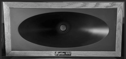
which is about the right size to replace the 2380, looks pretty cool, and is available in a kit form that's reasonably priced. Here's the website with some specs (
http://www.fastlaneaudio.com/eliptrac.html)
What do you think of this horn? Is it much better than the JBL 2380A for this application w/ the TAD 4002? I also have a pair of JBL 2446H drivers. Is this driver better than the TAD for this application? The TADs have the original beryllium diaphragms, the 2446's have titanium diaphragms from Orange county speaker.
Thanks again for your help and guidance. I look forward to your response
-H


.

 Reply With Quote


