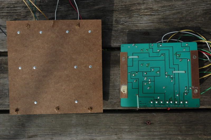
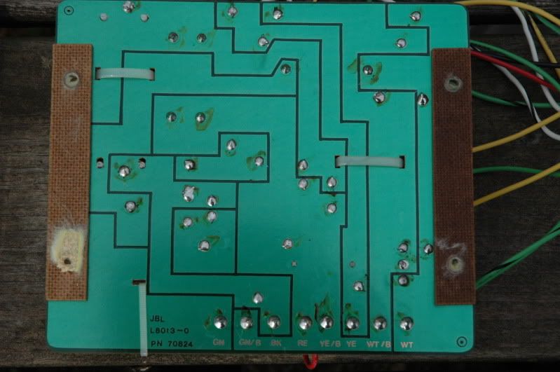
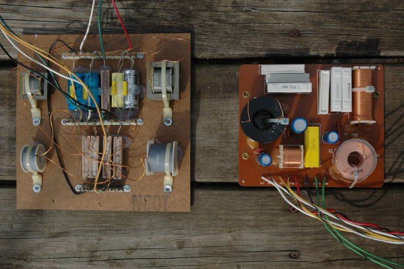
Long time lurker, recently registered. I am looking for an image of the solder side of a JBL L100t crossover. I am the original owner of a pair and would like to rebuild the crossover. I have new caps in hand, (Solens and Daytons). I want to etch new (larger) PCBs to accomodate the larger capacitors. Unfortunately, the speakers are at our other home and I have the parts and free time now. Thanks.

 Reply With Quote