Page 2 of 2 FirstFirst 12
Results 16 to 22 of 22

Thread: UREI 813C Expertise needed

  1. #16
    Senior Member
    Join Date
    Feb 2009
    Location
    annapolis, md usa
    Posts
    706
    Quote Originally Posted by Earl K View Post
    Rusty,


    - As RobH pointed out ( as well as subwoof ) / wire the 3 drivers according to what you see in that schematic .

    - As to reconciling the wiring in the posted schematic, to what you and Oldmics have observed / here's what you both need to know ;

    "Polarity Checkers are very unreliable devices when used on ( passive or electronic ) "all-pass" networks ( & thats what that Urei network is ) .
    - ie; They can give a false reading .

    - The delay derived from an all-pass network is frequency dependent ( so all the phase changes go through multiple 360 deg. rotations ) .
    - This makes "polarity" a moving target over the operating range of the transducer .

    - One typically doesn't encounter this when dialing in a delay on a digital speaker management system ( such as Oldmics typically uses ) .
    - One always encounters this phenomenon when using older analog crossovers that offer a simple "delay" adjustment on only the woofer section ( such as I continue to use ) .

    <> EarlK
    Thanks Earl, I appreciate your explanation.

    My only previous experience with a phase tester involved watching someone set up a 4 way studio monitor system that utilized a digital crossover.

    First chance I get (speakers are set up at someone else house) I'll remove the 801C and reverse the leads on the mid woofer to match the Urei decal/schematic (the other drivers already do), and reverse the speaker leads, as the preamp inverts phase.

    I'll see if I can't talk Oldmics into coming over and doing some tests in the next few weeks.

  2. #17
    Senior Member
    Join Date
    Feb 2009
    Location
    annapolis, md usa
    Posts
    706
    Quote Originally Posted by subwoof View Post
    All older JBL transducers are polarity noted by this:

    when placed facedown on a surface, the red terminal is on the right ( right on red ).

    This convention means that the "outward displacement / positive" terminal is the black ( left ).

    HOWEVER it is very important to wire the cabinets as designed ( and as pictured on the schematic ) for proper performance. And yes it is COMMON to find HF or MF components wired " out of phase " on certain systems.

    Absolute phase integrity is not a prerequisite to correct sound.

    sub
    Okay, I should have updated this thread long ago, but just thought about it. Apologies for any confusion derived from my original inquiry into wiring up a pair of 813C speakers. When taken apart after purchase, the internal wiring neither matched one another (left/right speakers wired differently), or the schematic. Hence, my confusion.

    I found the manual that came with the speakers online somewhere and have scanned the pertinent pages here for posterity (I think). Near the bottom of page 2 it says: "Positive voltage applied to the red terminal will cause forward motion (toward the listener) of the woofer cones."

    Page 3 then has a table at the bottom of the page showing the color coding of the driver terminals. Note the asterisk on the brown wire, and comment stating: "There is a red plastic cable tie on this lead as a reminder to connect it to the red terminal." This is of course reverse of what is shown on the schematic, which is Brown going to "-" (though on the "right" in the diagram). I looked at the crossover wiring harness that was replaced and did find a small red cable tie on 1 of the 2 brown wires.

    Anyway, when put back together, I re-wired them following the chart in the manual (and schematic) for the coax, and then placed the Brown wire to Red and Yellow wire to Black on the helper as stated in the manual. Both the coax and helper woofers move outward on a positive charge, as I believe is intended. Hope this helps others in the future.
    Attached Images Attached Images  

  3. #18
    Senior Member
    Join Date
    Feb 2009
    Location
    annapolis, md usa
    Posts
    706
    Second try.
    Attached Images Attached Images

  4. #19
    Senior Member
    Join Date
    Apr 2003
    Location
    GTA, Ont.
    Posts
    5,110
    Thanks Rusty!,

    The problem now is that if you followed RobH & SubWoofs advice ( which is correct IMO ) you would have attached the Red wire ( of the HF circuit ) to the Black terminal of the 2425HS driver.
    - Doing so means all 3 drivers will move together in the same direction when a positive pulse is applied.
    - That's consistent with how I read the schematic.
    - That's also consistent with how I believe a studio monitor should react ( ie; no flipped polarities ).
    - At one point back in the early 80's ( when THX was born ) this was pushed as a new standard ( ie; flipped polarities were forbidden if they were to simply fix phase problems at crossover when those problems could be fixed with delay networks & different > steeper acoustic slopes ).

    Unfortunately, the schematic itself is in direct opposition to the printed chart ( found on page 3 of the document that you just posted ) when it comes to the HF driver.
    - Therefore, I feel the directions on page 3 ( for the HF wiring ) are wrong.


  5. #20
    Senior Member
    Join Date
    Feb 2009
    Location
    annapolis, md usa
    Posts
    706
    Earl, Not sure I follow. Schematic and manual show both show RED + wire to Red terminal on the 2425h.

  6. #21
    Senior Member
    Join Date
    Apr 2003
    Location
    GTA, Ont.
    Posts
    5,110
    Quote Originally Posted by rusty jefferson View Post
    Earl, Not sure I follow. Schematic and manual show both show RED + wire to Red terminal on the 2425h.
    Hi Rusty,

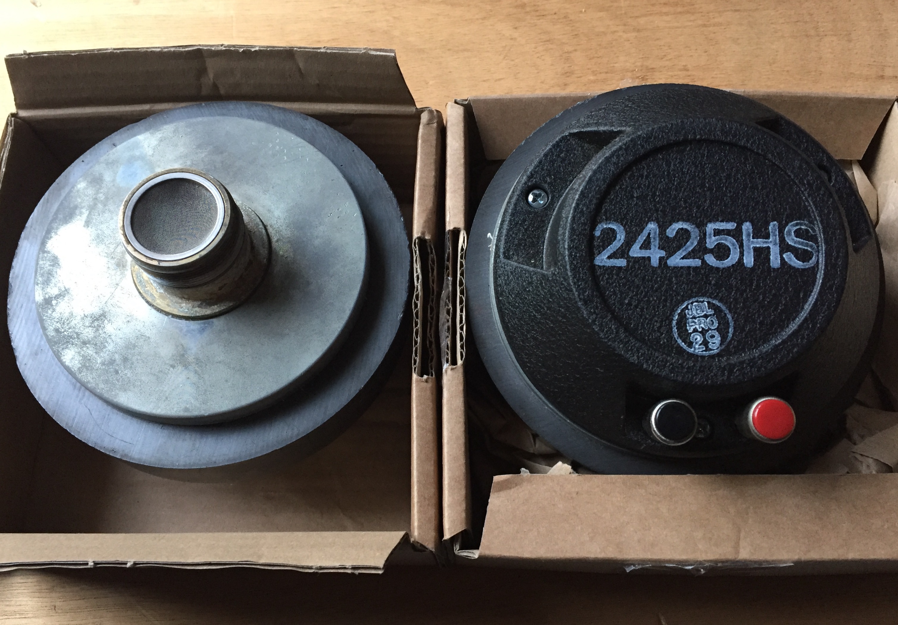
    Well, I don't have any 2425HS here ( just plain old 2425H, 2426H & 2427H ) and all of them when oriented with the terminals down ( as shown in the schematic pic, with the driver exit pointing away from the viewer ) have the black terminal to the left ( & red terminal to the right ).

    Maybe your 2425HS drivers have had the actual terminal hardware switched around from normal JBL protocol ( ??? ) .

    See below : ( black terminal = "+" at the JBL driver, the schematic has the red wire going to it [black] in the pictogram )


  7. #22
    Senior Member
    Join Date
    Feb 2009
    Location
    annapolis, md usa
    Posts
    706
    Earl, my 2425hs drivers are like the ones pictured, but I think I understand your explanation now. You're saying the positive connection to each driver should be on the left side terminal of each driver regardless of what color the terminal is. The association of Red being "+" is ignored at the driver. Both woofers do move out on the positive charge to the left side terminals. The 2215h is painted Black, and the 801 has a "+" mark. Interesting way of labeling things. I don't know if I'll hear a difference switching the 2425hs, but I can check. Accidentally reversing the connection on the 2215h is obvious, if you've heard the speakers properly wired. Interesting such a possible discrepancy between schematic and the manual regarding the HF driver?

Thread Information

Users Browsing this Thread

There are currently 1 users browsing this thread. (0 members and 1 guests)

Similar Threads

  1. Urei 813C
    By lpd in forum Lansing Product General Information
    Replies: 15
    Last Post: 02-07-2007, 02:07 PM
  2. Urei 813C
    By mikebake in forum Lansing Product General Information
    Replies: 5
    Last Post: 02-24-2004, 02:14 PM

Posting Permissions

  • You may not post new threads
  • You may not post replies
  • You may not post attachments
  • You may not edit your posts
  •