Results 1 to 15 of 60

Thread: Am I building these correctly - JBL 4355 Crossovers

Hybrid View

Previous Post Previous Post   Next Post Next Post
  1. #1
    Senior Member
    Join Date
    Apr 2007
    Location
    Maryland
    Posts
    481

    Am I building these correctly - JBL 4355 Crossovers

    All,

    Please forgive me, but I have never built crossovers before (I'm not even sure if I am reading the schematics correctly). I was hoping some one can verify whether I am building the crossovers correctly. I have included below the original schematics posted by Giskard, followed by my drawing of how I plan to lay the various components. Could someone please look this over for me?

    Thanks in advance

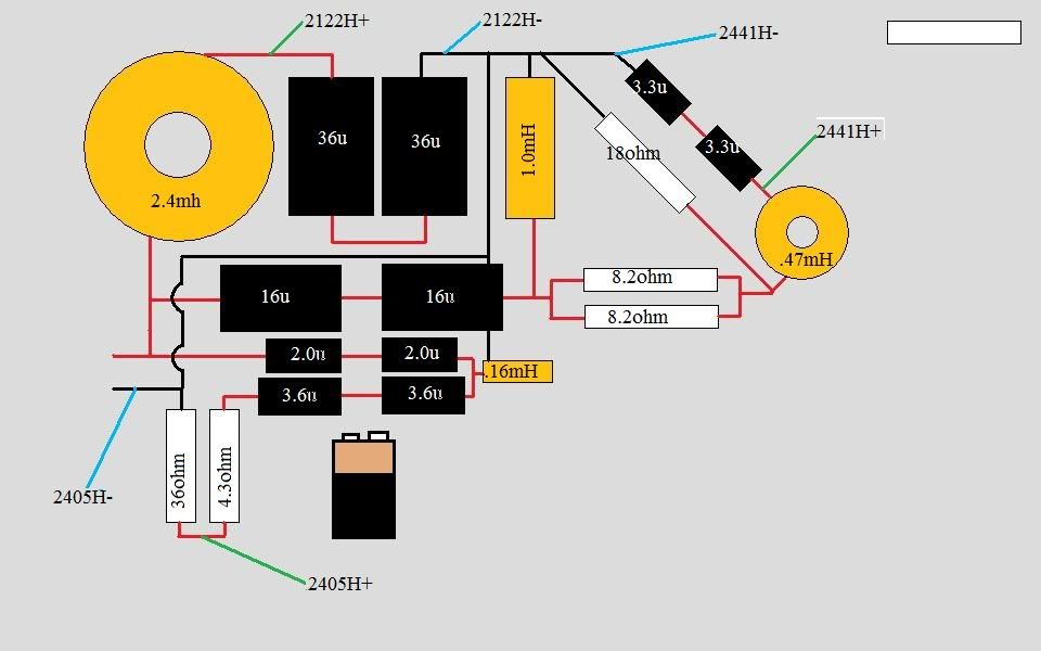
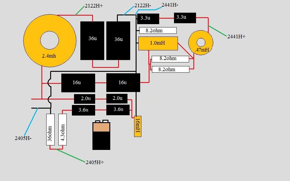
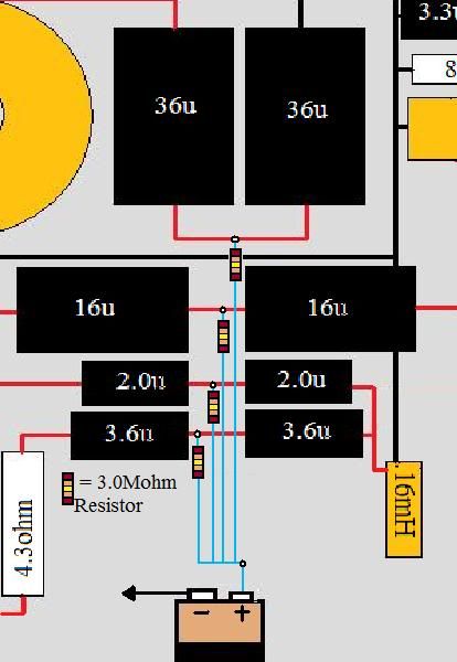
    Original Schematics:


    My Diagram:


  2. #2
    Senior Member
    Join Date
    Apr 2007
    Location
    Maryland
    Posts
    481
    anyone?

  3. #3
    Senior Member jerv's Avatar
    Join Date
    May 2006
    Location
    Norway
    Posts
    185

    Looks ok to me

    Quote Originally Posted by dkalsi View Post
    anyone?
    Your drawing looks good to me. (I guess L-pads are placed off the board somewhere else). Consider placing the inductors with 90 degrees orientation between each other to minimize interfecence. For tips on placement of inductors in crossovers, see http://www.troelsgravesen.dk/coils.htm

  4. #4
    Senior Member
    Join Date
    Apr 2007
    Location
    Maryland
    Posts
    481
    Quote Originally Posted by jerv View Post
    Your drawing looks good to me. (I guess L-pads are placed off the board somewhere else). Consider placing the inductors with 90 degrees orientation between each other to minimize interfecence. For tips on placement of inductors in crossovers, see http://www.troelsgravesen.dk/coils.htm
    Thanks Jerv,

    Yes - the L-pads have not been included in the diagram. Per the link you provided (thanks!), I moved/oriented the inductors a little bit differently. See revised diagram below. Additionally, I have also included a picture of how I was planning on charge coupling the capacitors - does this also look right?

    Thanks Dhar

    New Orientation:


    Charge-coupling the capacitors:

  5. #5
    Senior Member
    Join Date
    Apr 2007
    Location
    Maryland
    Posts
    481
    142 views and only 1 reply? Could some one please verify whether I have the charged coupled methodology correct, and whether this symbols below represent positive input:


  6. #6
    Administrator Robh3606's Avatar
    Join Date
    Apr 2003
    Location
    Rocinante
    Posts
    8,200
    Yes those are the positive feeds. The CC topology looks fine.

    Rob
    "I could be arguing in my spare time"

  7. #7
    Senior Member jerv's Avatar
    Join Date
    May 2006
    Location
    Norway
    Posts
    185
    Quote Originally Posted by dkalsi View Post
    Thanks Jerv,

    Yes - the L-pads have not been included in the diagram. Per the link you provided (thanks!), I moved/oriented the inductors a little bit differently. See revised diagram below. Additionally, I have also included a picture of how I was planning on charge coupling the capacitors - does this also look right?
    Sorry about not being able to answer earlier - your layout looks good to me, and I also second Rob's comment on the CC topology. Good luck with the building!

    Regards, Espen

  8. #8
    Senior Member
    Join Date
    Apr 2007
    Location
    Maryland
    Posts
    481
    Just realized that I had made an error when I revised the inductor placement. I incorrectly labeled the 18ohm resistor as 8.2 ohm and I had a positive lead coming out from 1.0mH inductor when it should have being coming from the 18 ohm resistor.

    See revised diagram below (just in case someone is following this thread).

  9. #9
    Obsolete
    Join Date
    Apr 2003
    Location
    NLA
    Posts
    12,193
    For further clarification:


    The LEAP schematic is correct. Ignore R10, R11, R12 and R13, R14, R15. They were used to simulate L-Pads at 50% power reduction. A person would use L-Pads instead. 16-ohm L-Pad on the 2441 and 8 ohm L-Pad on the 2405. The coils are standard Solen coils with DCR values lower then 0.5 ohm. The capacitors are Solen PB capacitors, the smaller sized poly caps. If I remember correctly, the PA caps were the larger, higher voltage caps.

    Unfortunately this LEAP schematic doesn't show exactly how to bias capacitors, that knowledge is assumed based on many past discussions and posted schematics. One can use either the battery method as shown in many JBL schematics or the diode method as shown in the 4365 schematic.

  10. #10
    Senior Member martin2395's Avatar
    Join Date
    Apr 2012
    Location
    Europe
    Posts
    928
    In a well dampened room they 'll do without the L-pads but YMMV.

    Also - save money for good caps, I'm paying the price for buying the cheap crosscaps.
    Something like Mundorf S/G/O or maybe some soviet-era PIO's should be miles better.

  11. #11
    Senior Member martin2395's Avatar
    Join Date
    Apr 2012
    Location
    Europe
    Posts
    928
    Very, very big thanks to member JBLPRO for noticing and letting me know that my hand drawn schematic of the 2441 HF section has a major flaw - the .47mH coil should we wired in series, not in parallel

    Now I have to fix both networks

  12. #12
    Member JBLPRO's Avatar
    Join Date
    Mar 2015
    Location
    Kennett Square, PA
    Posts
    55
    Quote Originally Posted by martin2395 View Post
    In a well dampened room they 'll do without the L-pads but YMMV.

    Also - save money for good caps, I'm paying the price for buying the cheap crosscaps.
    Something like Mundorf S/G/O or maybe some soviet-era PIO's should be miles better.
    What caps did you use? I ordered Solen's all the way around but I am not at the listening stage yet. G Timbers recommends Solen's so i figured that would be a good choice.

    mk

  13. #13
    Senior Member martin2395's Avatar
    Join Date
    Apr 2012
    Location
    Europe
    Posts
    928
    I started with Jantzen crosscap (apparantly Tony Gee rates these higher than all the SCR's) but they were disappointing - harsh and grainy.
    Now I have the white Audyn Plus combined with Mundorf Supreme, only the 2123H is still running on 4x18uF Crosscaps because of cost and the sheer size of the Audyn caps.
    I'm also considering adding MKP1837 on those Crossaps to see if they make any difference on the midwoofer.

    Next step will be the resistors, I will be replacing the green Jantzens with Mundorf Mresist supremes.

  14. #14
    Senior Member martin2395's Avatar
    Join Date
    Apr 2012
    Location
    Europe
    Posts
    928
    Still happy with the 3155's. I changed the HF amp to a tube OTL and never been happier. I've heard many systems so far but I'd never trade my JBL's for anything else, expect maybe the DD series or some high end custom TAD's.

    However I still don't understand the need for a highpass for the 3155 (the need for lowpass for 2235H is obvious as it's directly coupled to the amp) as it makes you use an active crossover and a passive one behind it. or am I doing it wrong the whole time?

Thread Information

Users Browsing this Thread

There are currently 1 users browsing this thread. (0 members and 1 guests)

Similar Threads

  1. 4355 variant
    By Woody Banks in forum Lansing Product DIY Forum
    Replies: 21
    Last Post: 11-09-2017, 01:39 PM
  2. 4355 Parts
    By Nordwall in forum Lansing Product DIY Forum
    Replies: 4
    Last Post: 04-22-2010, 01:12 PM
  3. 4355
    By Techbot in forum System Information
    Replies: 1
    Last Post: 05-04-2006, 03:11 AM
  4. 2202h in 4355
    By Dwight in forum Lansing Product General Information
    Replies: 5
    Last Post: 10-11-2003, 07:36 PM

Posting Permissions

  • You may not post new threads
  • You may not post replies
  • You may not post attachments
  • You may not edit your posts
  •